M Motor Actuators
—
Y20EBD Valve Linkage for M100 Motor Actuators 23
Checkout Procedure
After Installation and adjustment, run the system through several complete
open/close cycles to be sure that all components are functioning correctly.
Check to be sure that the actuator responds to the controller and operates
the valve properly. Check for proper voltage. Check for operation of the
linkage without binding.
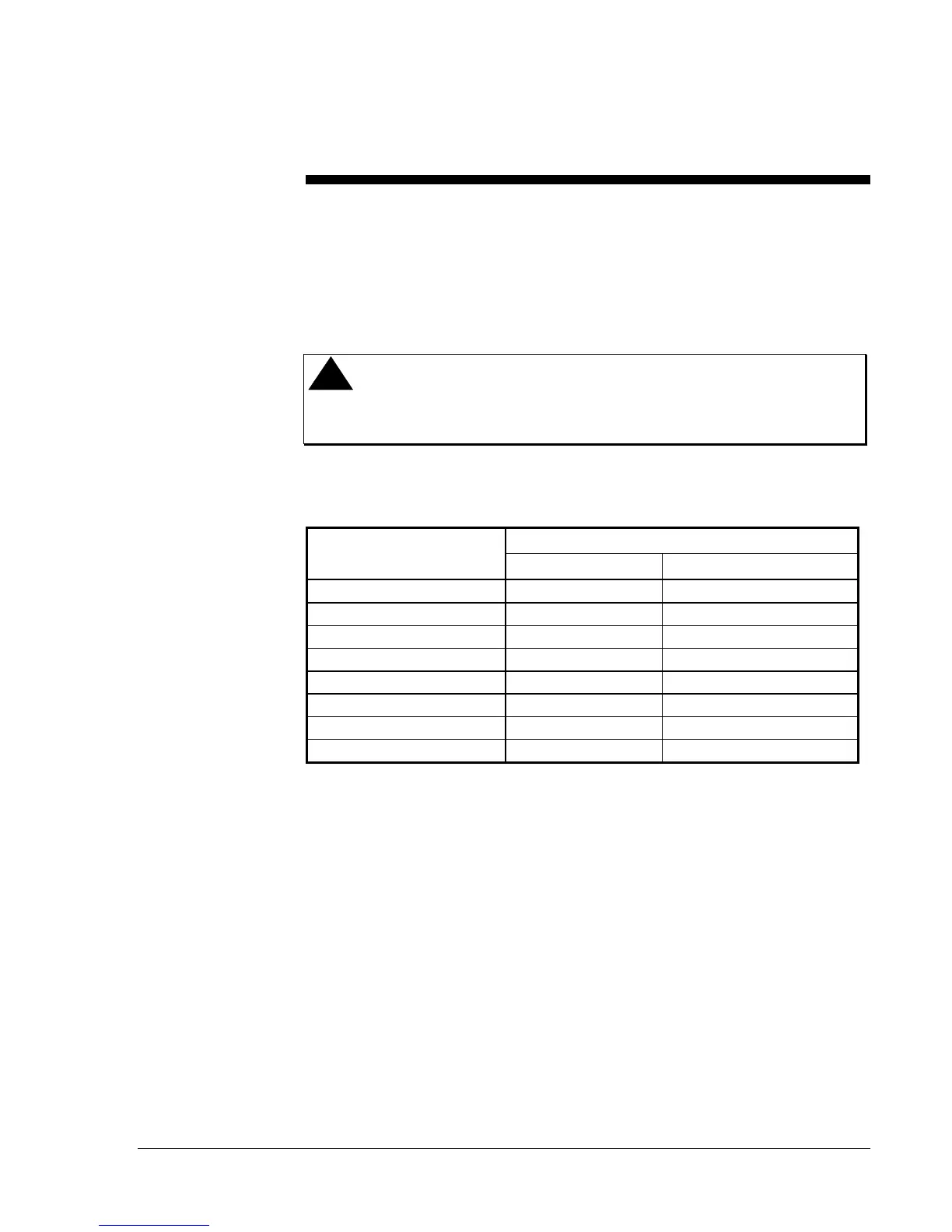
!
CAUTION: The actuator should not be stalled by the valve. The
actuator may be damaged if it is not free to complete
its full stroke.
Table 2: Actuator Connections for Travel Limit Adjustment
Jumper Terminals
Model Clockwise (CW) Counterclockwise (CCW)
M100A
1 and 2 1 and 3
M100C
COM to CW COM to CCW
M100E
S1 to S2* Disconnect S1, S2, A, C
M100F
8 and 9 8 and 10
M100G or M100H
8 to T1 8 to 10
M100J
8 and 9 8 and 10
M100Q
8 to T1 8 to 10
M100M
R to B Disconnect R from B
*
Apply 24 VAC to relay terminals A and C for clockwise rotation.
Note: On all models, remove controller wires and apply 24 VAC to
terminals T1 and T2 while making adjustments. Spring return
models will go full CCW when power to T1 and T2 is removed.
 Loading...