44 A.0500.301/314.C – IM-TW/10.00 GB (0401)
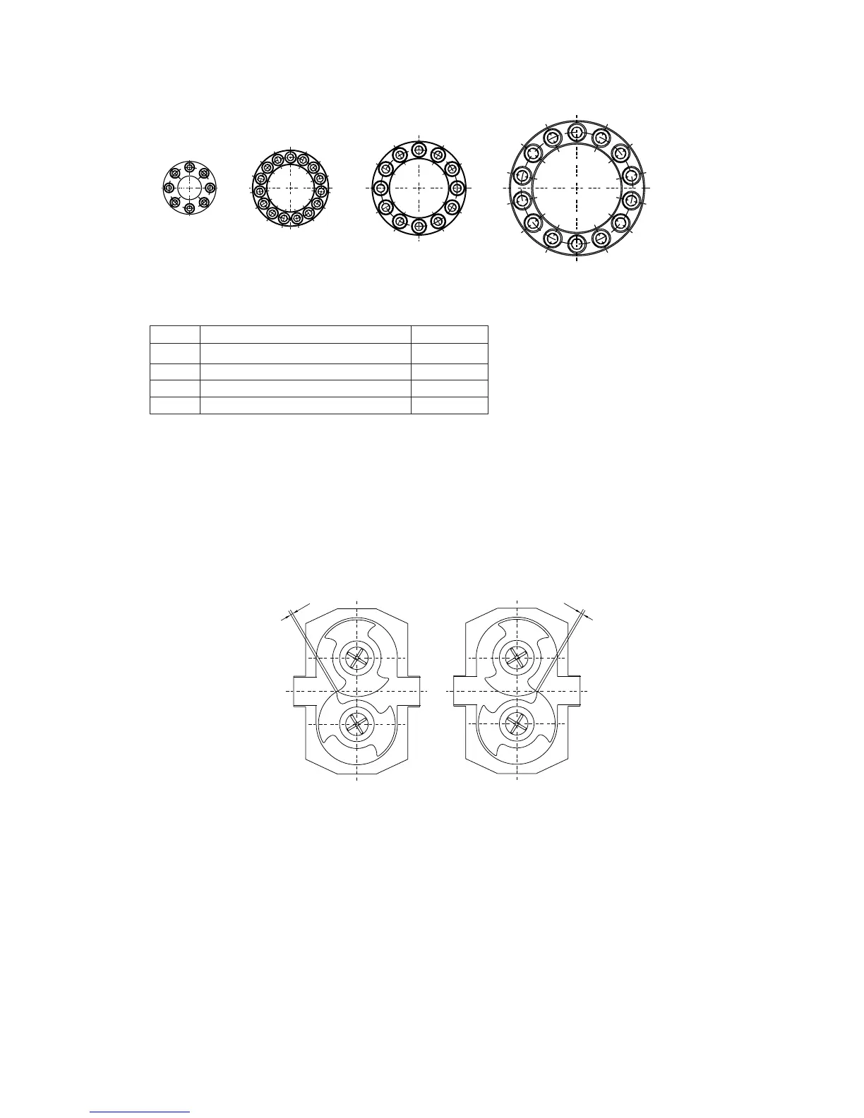
TW1 TW2 TW3
TW4
1
4
8
12
2
6
9
3
7
11
10
5
1
3
13
10
6
2
8
12
4
14
9
5
1
7
11
15
3
5
7
2
4
6
8
1
5
9
13
4
8
12
2
6
10
14
3
7
11
X
X
TW1 TW2 TW3 TW4
4.7.6 Synchronization of the rotors
4.7.6.1 Manual synchronization
1. Position the rotors by turning the drive shaft manually to the position shown in the
diagram.
Check the clearance between the rotors with a gage blade.
In both positions dimension X should be the same.
2. Place a block of soft material between the rotors to lock them against each other.
3. Tighten now the screws of the locking assembly/elements in the same way as
described for the lay shaft.
4. Check the clearance between the rotors, turn the drive shaft 180° and check the
clearance in this position also. In both positions dimension X should be the same.
5. Remove the retainers and rotors.
Pump Description Torque [Nm]
TW1 Allen screw DIN 912 M5x20 (12.9) 8.5
TW2 Allen screw DIN 912 M6x18 (12.9) 9
TW3 Allen screw DIN 912 M8x22 (12.9) 22
TW4 Allen screw DIN 912 M10x25 (12.9) 42



 To Next Page