2
Figure 2
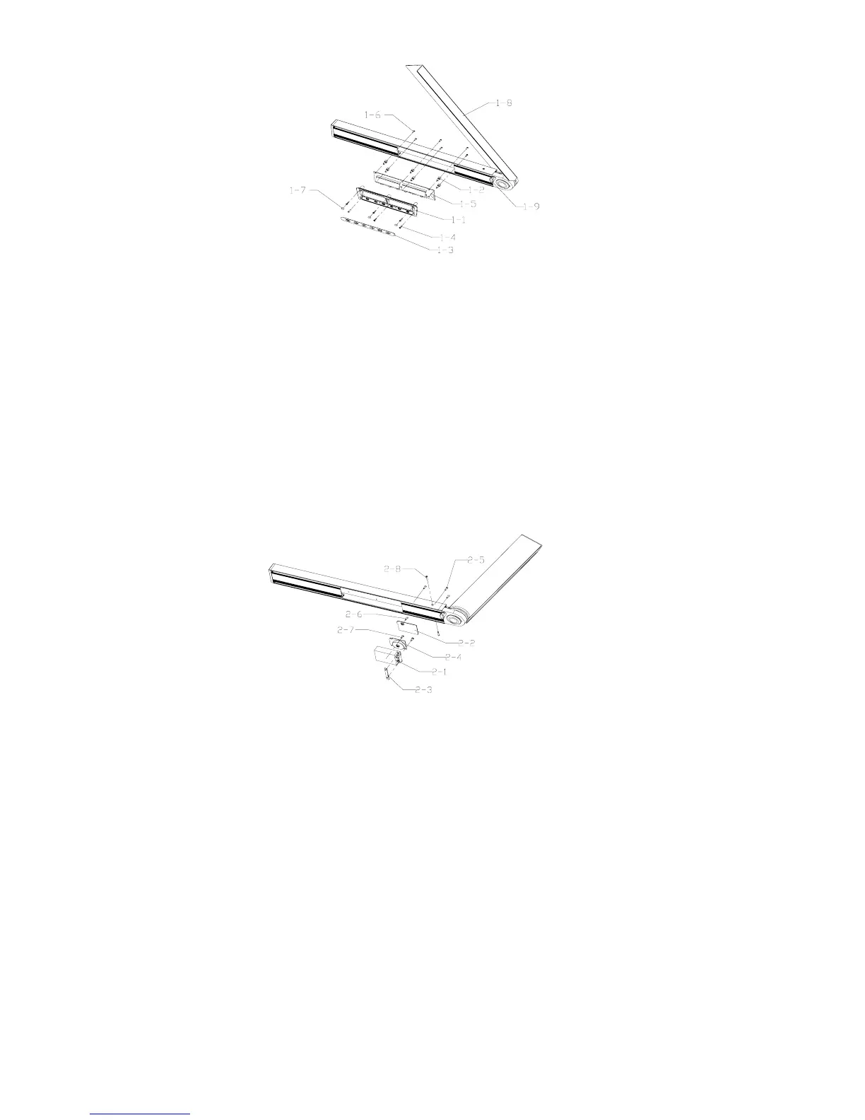
1-1 Keypad 1-4 Crosshead Plate Bolt M2.5×10 1-7 Bolt Cover
1-2 Connecting Staff 1-5 Main Circuit Board 1-8 Angle Square Board
1-3 Membrane 1-6 Crosshead Sunk Bolt M2.5×8 1-9 Lock Knob
2). Disassembly of horizontal-angle sensor parts
(1) Turn the angle square board by a certain angle.
(2) Disassemble the 3pcs crosshead sunk bolts M3×10
(
2-5#
)
and 2pcs crosshead sunk bolt M2.5×25
(
2-8#
)
, pull
out the horizontal-angle sensor parts, and take off the press plate (2-3#).
(3) Disassemble the crosshead sunk tapping bolt ST2.5×10(2-6#), and unclench the cover board
(
2-2#
);
(4) Disassemble the crosshead plate tapping bolt ST2.2×6.5(2-7#), then disconnect the sensor shell (2-1#)and the
sensor circuit board(2-4#)
Figure 3
2-1 Sensor Shell 2-2 Cover Board of Shell 2-3 Press Plate
2-4 Sensor Circuit Board 2-5 Crosshead Sunk Bolt M3×10
2-6 Crosshead Sunk Tapping Bolt ST2.5×10 2-7 Crosshead Plate Tapping Bolt ST2.2×6.5
2-8 Crosshead Sunk Bolt M2.5×25
1.3 Disassembly of laser parts
(1) Unclench the laser cover (3-3#)
(2) Turn the angle square board by a certain angle.
(3) Disassemble the 4pcs crosshead sunk bolts M2.5×6(3-5#), pull out the left-end cover parts, and disassemble the
power leading wire.
(4) Disassemble the 2pcs crosshead plate bolts M2×6
(
3-7#
)
, and then disassemble the leading wire of light source,
i.e. disassemble the circuit board of light source (3-4#).
(5) Disassemble the 3pcs crosshead plate bolts M2.5×10(3-6#); then disconnect the left-end cover (3-2#) and the
light source parts (3-1#).