3
Figure 4
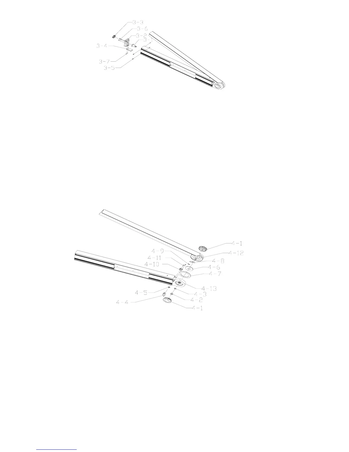
3-1 Light Source Parts 3-4 Light Source Circuit Board 3-7 Crosshead Plate Bolt M2×6
3-2 Left End Cover 3-5 Crosshead Sunk Bolt M2.5×6
3-3 Laser Cover 3-6 Crosshead Plate Bolt M2.5×10
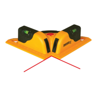
1.4 Disassembly of ruler body parts
(1) Screw off the lock knob (4-4#), and disassemble the gasket φ6 (4-5#);
(2) Screw off the 2pcs crosshead plate bolts M2.5×8(4-11#), and disassemble the press plate (4-10#).
(3) Unclench the 2pcs protecting covers (4-1#) on both ends.
(4) Loosen the hexagon nut M6 (4-2#) and take off the gasket φ6 (4-3#), i.e. disconnect the mainframe parts (4-13#)
and the angle square board parts (4-12#)
(5) Disassemble the spacer (4-7#) from the mainframe, and unclench the including angle sensor (4-6#).
(6) Disassemble the electrical brush (4-9#) and the electrical brush seat (4-8#) from the angle square board.
Figure 5
4-1 Protecting Cover 4-5 Gasketφ6 4-9 Electrical Brush 4-13 Mainframe Parts
4-2 Hexagon Nut M6 4-6 Included Angle Sensor 4-10 Press Plate
4-3 Gasketφ6 4-7 Spacer 4-11 Crosshead Plate Bolt M2.5×8
4-4 Lock Knob 4-8 Electrical Brush Seat 4-12 Angle Square Board Parts
Note: All the above is the general dissembling course of 40-6065, and the assembling course of 40-6065 is
just the contrary. While repairing the instrument, it should take the disassembling level, procedure and
method according to the practical situation.
2. Accuracy Check and Calibration
This function works only when the angle is in “UNLCOK” state.