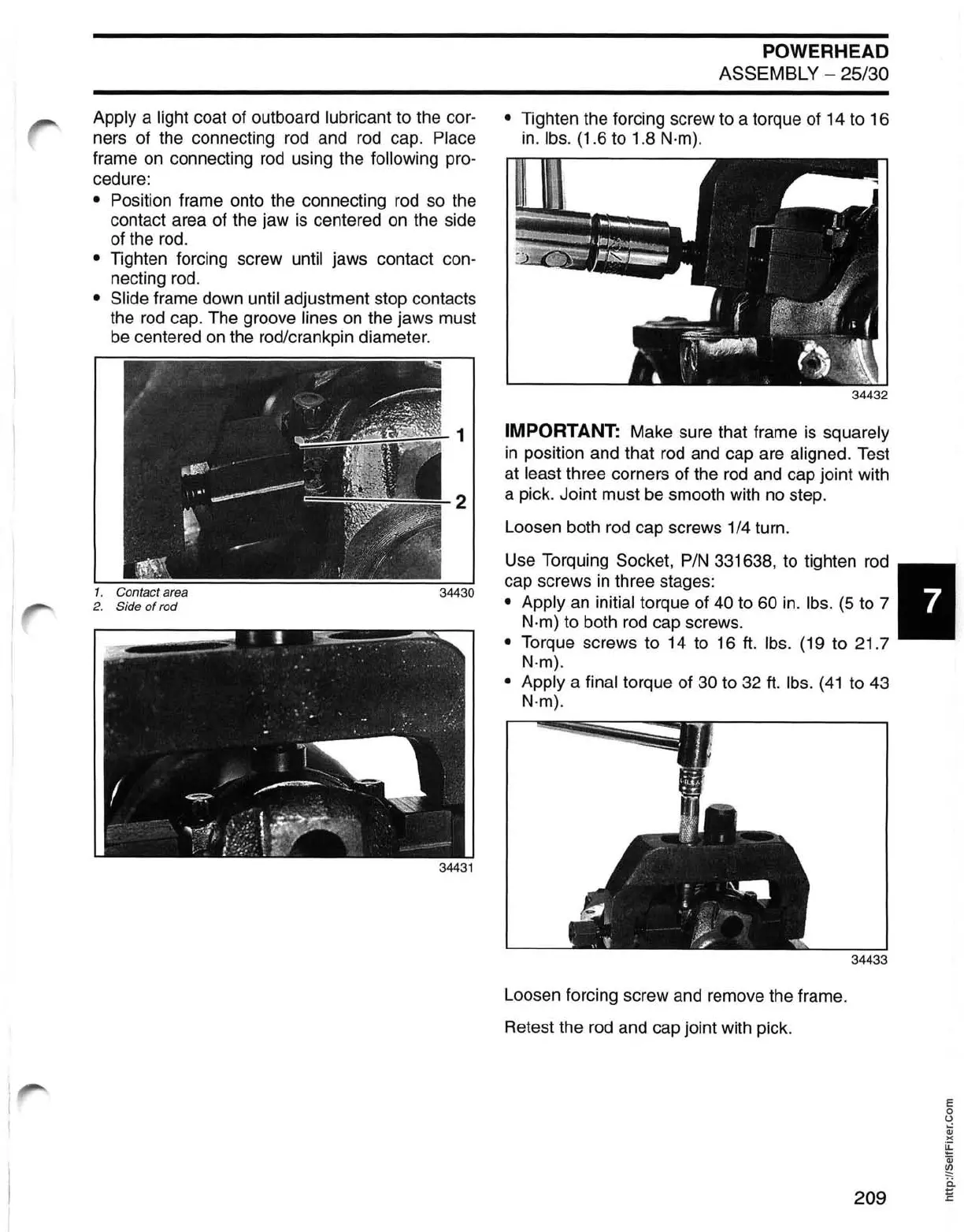
Apply a light coat of outboard lubricant to the cor-
ners of the connecting
rod
and rod cap. Place
frame
on
connecting
rod
using the following pro-
cedure:
• Position frame onto the connecting rod
so
the
contact area of the jaw
is
centered
on
the side
of the
rod.
• Tighten forcing screw until jaws contact con-
necting
rod.
• Slide frame down until adjustment stop contacts
the
rod
cap. The groove lines
on
the jaws must
be
centered
on
the rodlcrankpin diameter.
POWERHEAD
ASSEMBLY - 25/30
• Tighten the forcing screw to a torque of 14 to 16
in.
Ibs.
(1.6 to 1.8 N·m).
34432
1 IMPORTANT: Make sure that frame
is
squarely
in
position and that
rod
and cap are aligned. Test
at
least three corners of the
rod
and cap joint with
1. Contact area
2.
Side
of
rod
2 a pick. Joint must
be
smooth with
no
step.
34430
34431
Loosen both
rod
cap screws 1/4 turn.
Use Torquing Socket,
PIN
331638, to tighten
rod
7
cap screws
in
three stages:
• Apply
an
initial torque of
40
to 60
in.
Ibs.
(5
to 7
N·m) to both
rod
cap screws.
• Torque screws to 14 to 16
ft.
Ibs.
(19 to 21.7
N·m).
• Apply
a final torque of 30 to
32
ft.
Ibs.
(41
to 43
N·m).
Loosen forcing screw and remove the frame.
Retest the
rod
and cap joint with pick.
34433
E
o
o
:;j
)(
~
Qj
~
ii
209
~