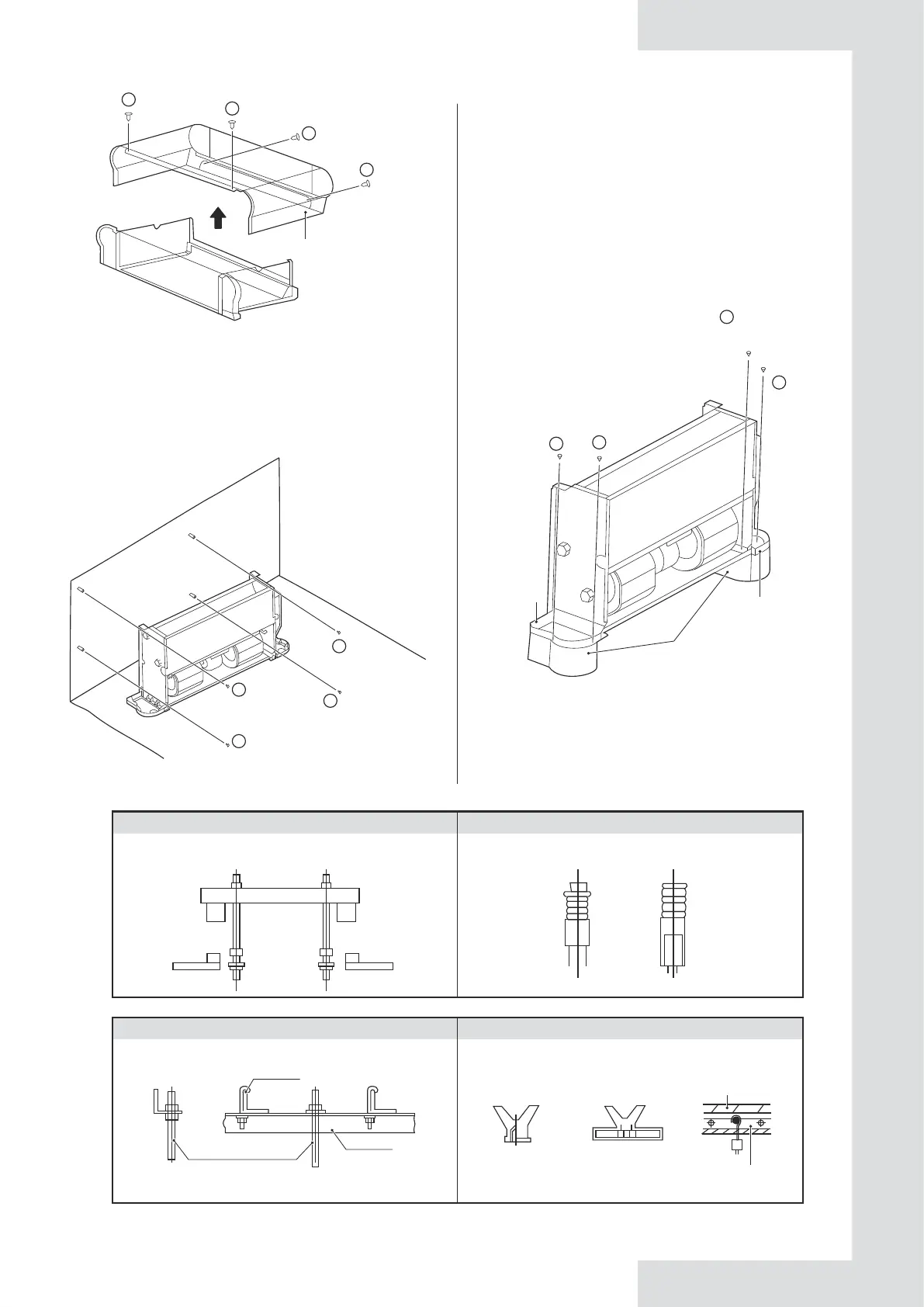
Figure 5-1
Figure 5-2 Diagram for fixing the unit body
Figure 5-4 Installation of lifting bolts
Mark the places for screws on the wall according to the
unit mounting holes or dimensions specified in Figure
5-12. The drain pipe for condensate water must be
smooth enough to allow unobstructed water discharge.
As shown in Figure 5-2, fasten four screws (①) into a
proper masonry structure.
The footings shown in Figure 5-3 are optional. You can
purchase them separately and install them as follows:
1. Put the footings beside the unit to be installed.
2. Place the mounting holes on the unit base into the
corresponding footing locating pin and install screws
①*2 and ②*2 to fix the footing according to Figure 5-3.
Figure 5-3
3) Install the unit following the steps below in case it
is ceiling mounted.
To match the existing structure, set the screw pitch
according to the unit dimensions.
2
2
1
1
1
1
1
1
Base
Footing
Base
Wood structure Original concrete slasb structure
Structure the square rod on the beam to
set the lifting bolts.
Use embedded bolts, and pull bolts.
Steel framework Newly set concrete slab structure
Directly set and use an angle steel for support. Set using embedded appliances, and embedded
type of bolts.
Knife-type
insertion piece
Sliding-type
insertion piece
Reninforced bar
Embedded bolt(hanging and
embedded bolt of piping)
Suspension bolt
Suspension bolt
Angle steel
for support
09
2
2
1
1
Casing
assembly