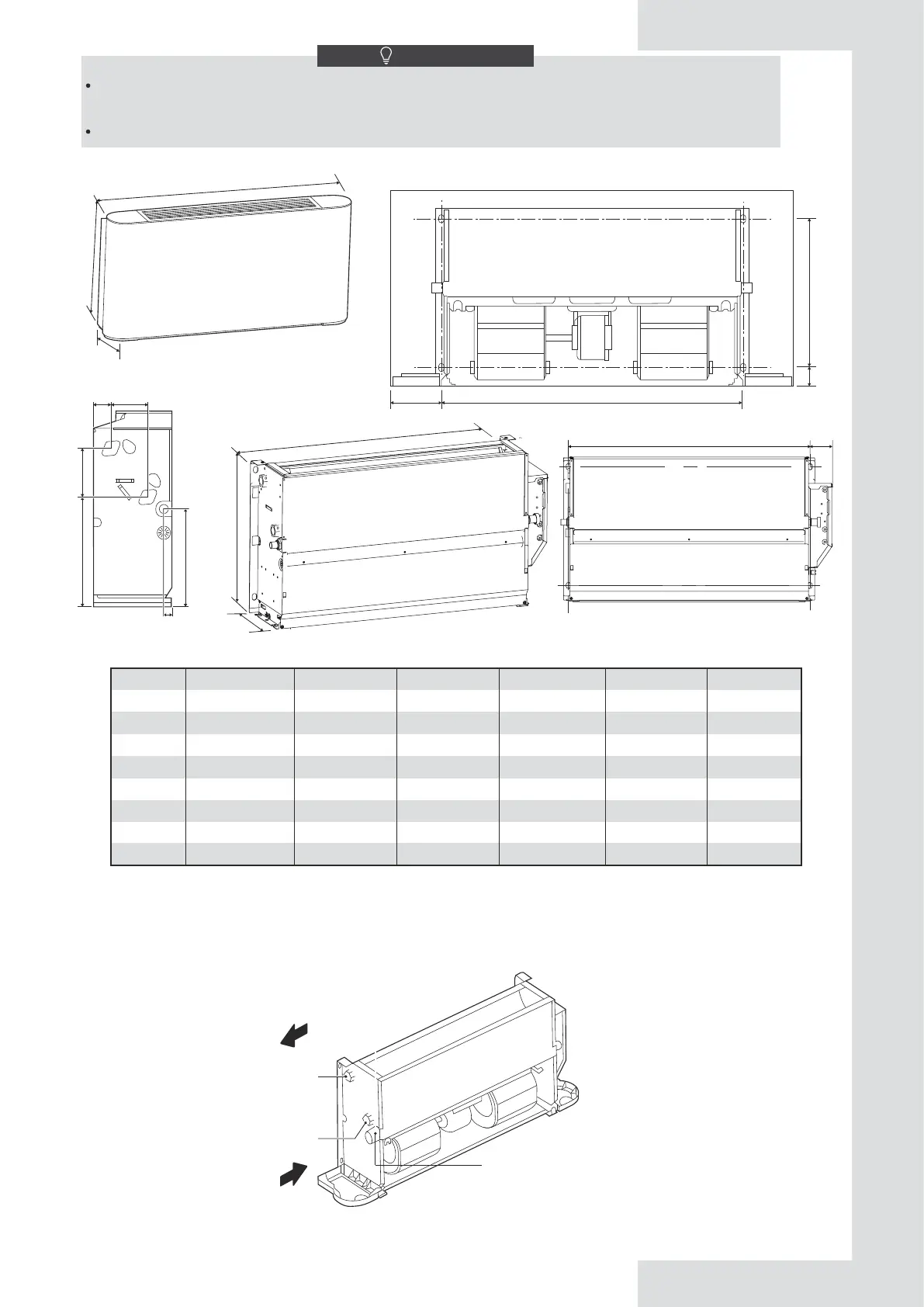
5.3.2 Dimensions
5.4 Liquid Pipe Connections
1) Only professionals can operate the liquid pipes.
Drain pipe must be the different side with the electric control box.
Connect the unit to the water system using inlet and outlet connectors.
Figure 5-12
Table 5-1 Unit: mm
Figure 5-13
NOTE
Do not consider the unit as a surface that can be relied on during actual use. Reserve enough space during installation for
ventilation purpose.
Using water or spray near the unit can cause electric shock and malfunction.
MODEL
A
B
C
D
E
F
MISTRALSU15
790
495
534
375
123
93
MISTRALSU25
1020
495
764
375
123
93
MISTRALSU35
1240
495
984
375
123
93
MISTRALSU50
1240
495
984
375
123
93
MISTRALSU70
1360
495
1104
375
123
93
MISTRALSU80
1360
591
1104
391
219
102
A
B
200
47 D
128 C
247
277 E
22
45 F
Water
outlet
Drainage
Water
inlet
11
Unit: mm
200
G
H
C 71
G
H
628
455
858
455
1078
455
1078
455
1198
455
1198
551