542933-UIM-C-0112
Johnson Controls Unitary Products 17
Heat kit configuration screens will appear in a communication system that includes a communicat-
ing variable speed air handler (indicated by a “-C” in the model number). For the AV/MV Air Handler,
the heat jumper must be located in the "On" position. For more information on the function of these
screens refer to the Service Mode section of this document.
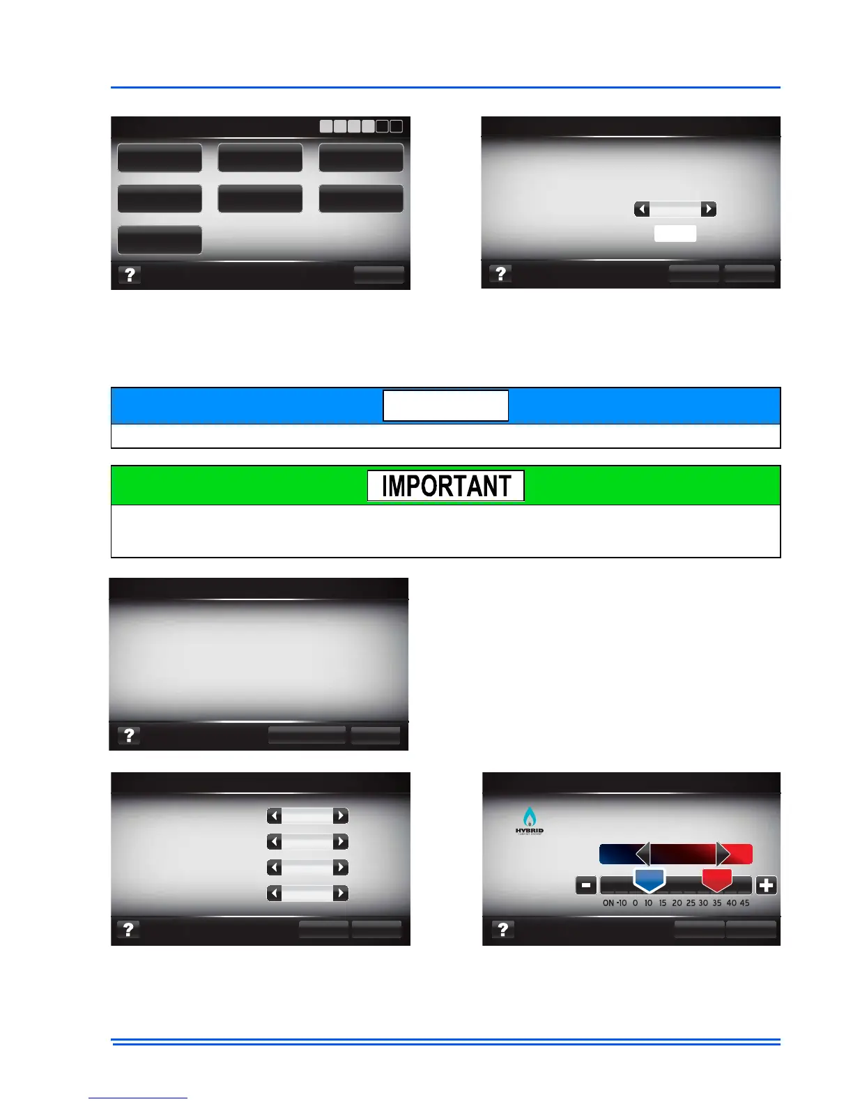
Heat Pump Configuration screens are only available in systems which contain communicating heat
pumps (denoted by a "-C" in the model number. For more information on the function of these
screens refer to the Service Mode section of this document.
The screen shown above is representative only. Actual heat kit models may vary.
If you have a system which has a heat kit installed, but did not see the heat kit configuration
screens, be sure to check the air handler control to insure that the heat kit jumper is on "Heat".
This only applies to the AV/MV Air Handler.
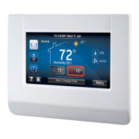
System ID screen will appear in every communi-
cating system install. This screen displays the sys-
tem ID that is used to identify system operation.
For more information about the system ID and
how the system will operate refer to Communicat-
ing Wiring Diagrams located on UPGnet.com.