542933-UIM-C-0112
6 Johnson Controls Unitary Products
SECTION IV: WIRING COMMUNICATION
All wiring must comply with local electrical codes and ordinances. Refer to Table 1 for terminal des-
ignations.
WIRING REQUIREMENTS
Standard 18 awg thermostat wires can be used to connect the communicating system.
Special (shielded) cable is not typically required. As with all communicating devices, it is a good
idea to keep wiring at least one foot away from large inductive loads. Examples of large inductive
loads include: electronic air cleaners, motors, etc. If these wiring practices are ignored, it may intro-
duce electrical interference (noise) which can cause erratic system operation.
SYSTEM WIRING OVERVIEW
The system is connected by four wires. Two of the wires are used to bring power into the individual
controls (R and C) and two of the wires are used for serial communication (A+ and B-). The plug/
harness that is provided in the kit should be used on the outdoor control.
Each Touch Screen Communicating Control Kit is equipped with a Communicating Plug Harness
(Fig. 5). This wire harness should be used for the wiring of the outdoor unit.
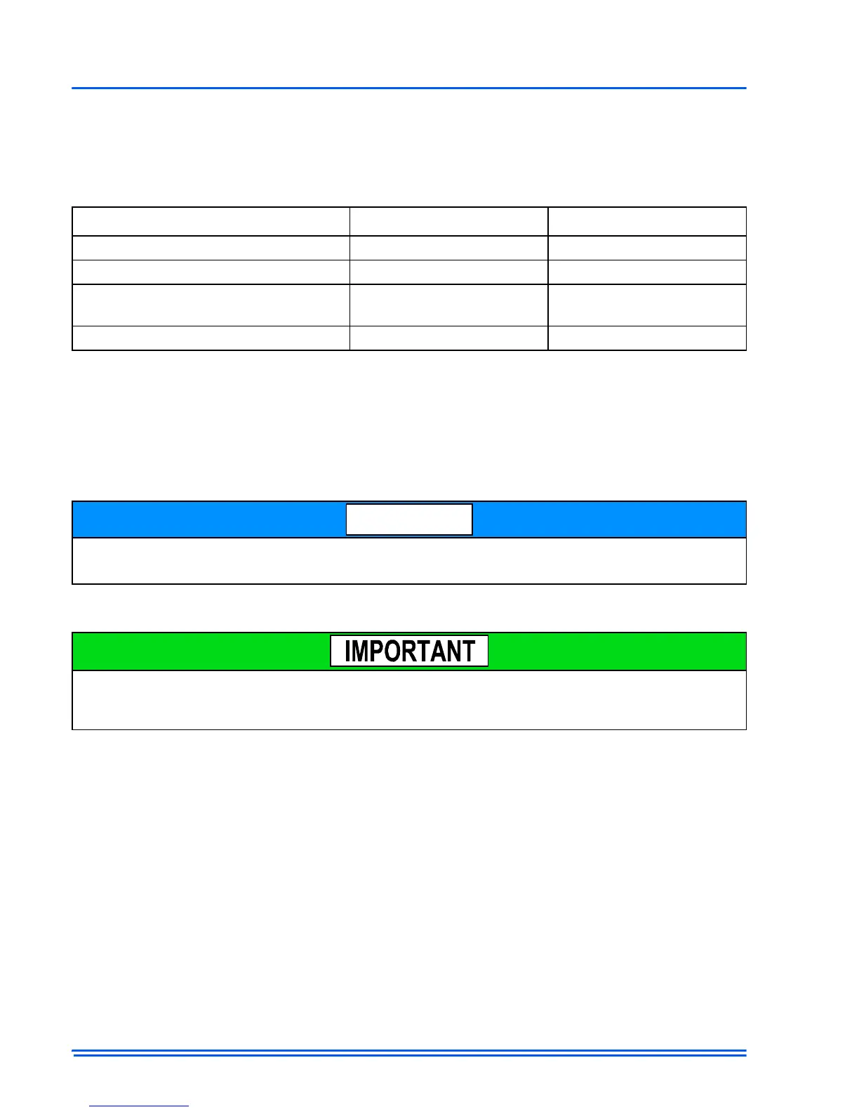
TABLE 1:
Terminal Designations
Signal Definition Label
Data Non-inverted signal A (+)
Low voltage power hot 24 VAC (Hot) R
Low voltage power common and data
ground
24 VAC (Common) C
Data Inverted signal B (-)
There may be installation applications where large inductive loads cannot be avoided. In these
cases shielded wire would be desired to ensure proper system functionality.
The communicating system requires 4 wires to operate. If installing a communicating system, be
sure to supply at least 4 wires to each unit/control. Below is a simple diagram showing the ideal
wiring path.