T7000 OWNER'S MANUAL T7000 OWNER'S MANUAL
JOHNSON COMMERCIAL TREADMILL
JOHNSON COMMERCIAL TREADMILL
08 09
• ATTENTION!
“AFTER INSTALLATION IS COMPLETED, THE TREADMILL WILL NEED TO BE CALIBRATED
BY USING THE AUTO CHECK FUNCTION (see MANAGER’S CUSTOM SETTING). IF THIS IS
NOT DONE, THE TREADMILL'S SPEED AND INCLINE VALUES MAY INCORRECT AND
DAMAGE THE TREADMILL."
DO NOT STAND ON THE BELT WHEN PERFORMING THE AUTO CHECK FUNCTION
• ASSEMBLY INSTRUCTIONS
To ensure the correct assembly of the T7000, please carefully follow these steps:
WARNING :
Please make sure that the power cord is unplugged during the completion
of the following procedure.
Part 4.
ASSEMBLY
Buttonhead
Cross Screw
Hex Head
Screw
Flat Hex-
Sockethead
Screw
Wave
Washer
Hex
Wrench
#5l Allen
Key
Cross
Screwdriver
T-Shape
Allen Key
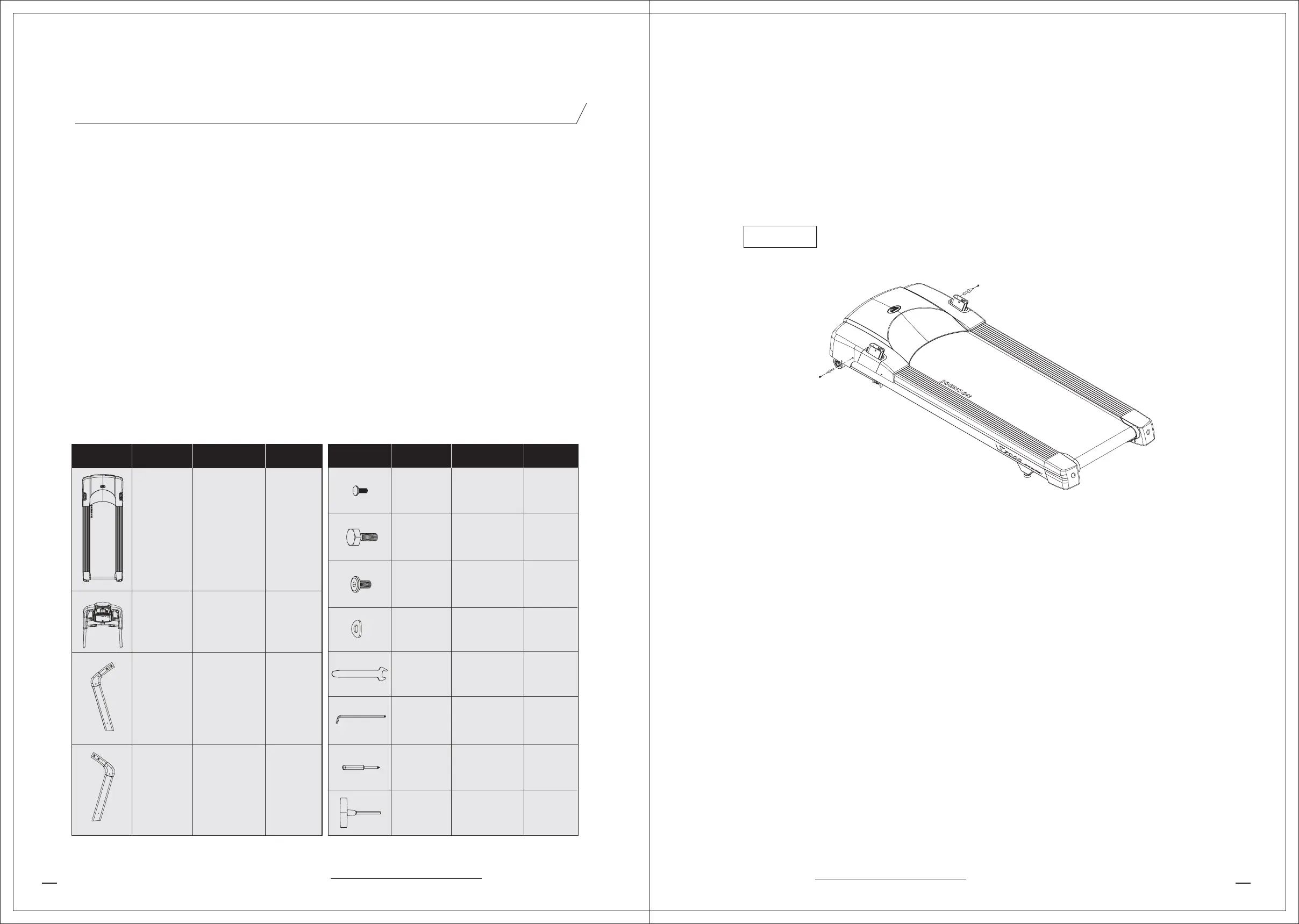
• ASSEMBLY PARTS AND TOOLS LIST
Drawing Parts No.
AB1 1
Z53
Z52
Z50
Z51
Z04
Z02
Z01
Z04
10
4
10
2
1
1
1
1
1
1
1
AN1
AC1
AC2
Frame
Set
Console
Set
Left
Console
Mast
Right
Console
Mast
Parts Name Quantity Drawing Parts No. Parts Name Quantity
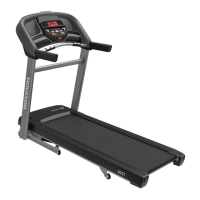
STEP 1 Remove The Motor Cover
Unscrew the left and right-size screws (Z53) and lift the motor cover off the treadmill and
set it aside. See Diagram 1.
STEP 2 Secure The Left And Right Console Mast
a.Attach the left console mast by placing it into the console mast support bracket and
aligning the mounting holes. Obtain five flat hex-sockethead screws (Z50) from the
Hardware Kit. See Diagram 2.
b.Lift up the plastic piece (Q05) attached aside the motor cover. Place 3 screws (Z50) on
the outside and 1 screw (Z50) on the inside and use the #5L Allen key (Z02) to secure the
screws, but leave room for adjustments. See Diagram 3.
c.Place a wave washer (Z51) on the screw (Z50) and secure the screw in the front of the
console mast. See Diagram 3.
d.Put down the plastic piece (Q05) on the motor cover. Place 2 screws (Z53) and secure
the screws into the frame. See Diagram 4.
e.Secure the right console mast to follow the above procedure.
Z53
Diagram 1