STEP 4 Replace The Motor Cover
Replace the motor cover on the treadmill using buttonhead cross screws (Z53) with the
cross screwdriver (Z01) to secure them. See Diagram 6.
STEP 5 Calibrate The Treadmill
Enter the Manager’s Custom Setting to select P13 AUTO CHECK to calibrate the treadmill’s
speed and incline values. After the completion of calibration, press EMERGENCY STOP key
to start the treadmill.
Z53
Diagram 6
T7000 OWNER'S MANUAL T7000 OWNER'S MANUAL
12
13
JOHNSON COMMERCIAL TREADMILL
JOHNSON COMMERCIAL TREADMILL
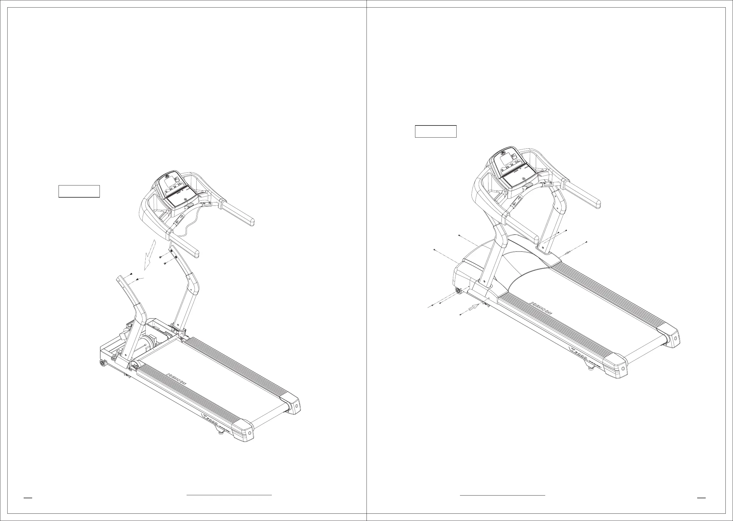
STEP 3 Attach The Console To The Console Mast
a.Route the display cable through the right console mast and pull it out of the hole on the
side of the console mast near the frame. Ask an assistant to hold the console in place
while you route the cable through the console mast. See Diagram 5.
b.Attach the console to the right and left console mast using four hex-head screws (Z52)
with the hex wrench to secure the screws.
c.Plug the cable connector into its receptacle on the lower board near the motor.
Diagram 5
Z52