V
3
V
4
V
8
V
7
V
1
V
2
V
6
V
5
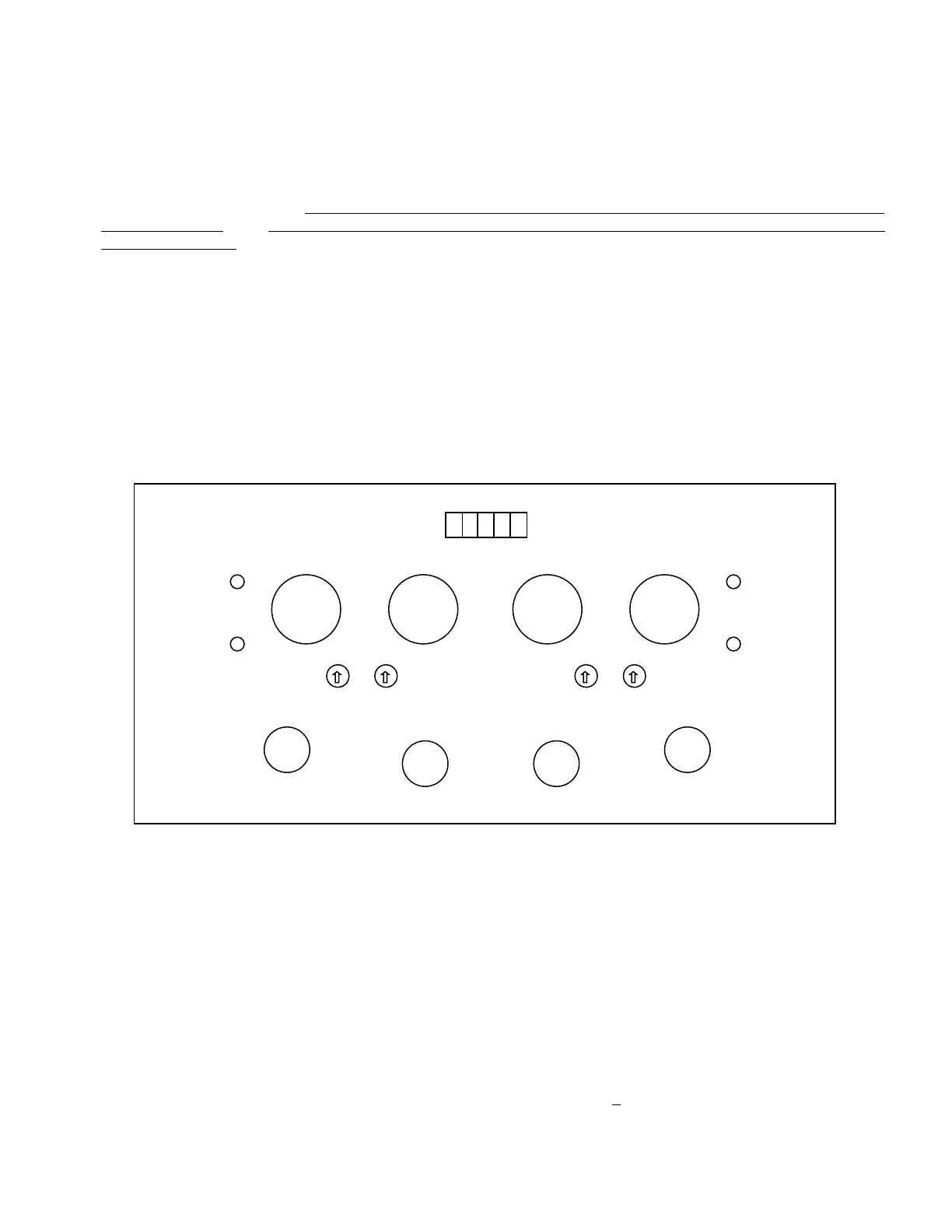
BIAS ADJ BIAS ADJ
EZ-BIAS
LED
EZ-BIAS
LED
V3 V4 V8 V7
3 4 0 8 7
EZ-BIAS
LED
EZ-BIAS
LED
on for one minute will not have the same bias after it has been operating for five hours. In other words, though
your bias may vary from time to time, we recommend leaving the bias alone after your initial adjustment.
4. Jolida has found that if the bias is incorrectly adjusted so that the electron tubes' bias levels are grossly out of
balance (more than 75% or in other terms more than 300 millivolts), a reduction in the life of the tube and other
problems can result.
5. It is important to note the V3, V4, V7, and V8 bias levels are increased by turning the bias adjustment
screw clockwise . The V3, V4, V7, and V8 bias levels are decreased by turning the bias adjustment screw
counter-clockwise.
Before you start. If you plan to use the E-Z bias system, the only tool you need will be a small plastic handled
flathead screwdriver to adjust the bias pots. If you wish to use the manual method, then you will also need a digital
multimeter (DC voltmeter probe used by electricians to test wall sockets) which can be purchased from any
electrical hardware store such as Radio Shack or Home Depot for as low as $15.
Biasing Layout
Top panel
Each of the 6550/KT88 tubes has two corresponding holes located below and to the outer edge of the amp. One
has a red LED that will light up once the proper bias level is reached. The other hole has a bias adj./bias trim pot,
which is used to adjust the bias to a given tube. Placing the screwdriver into it and turning the screwdriver
clockwise or counterclockwise will increase or decrease the bias level. There are two testing ports which hold a
five-slot socket with each slot corresponding with one of the bias trim pots. The probes of the multimeter are
inserted into these slots.
The following outlines the steps for biasing your amplifier. Please note that your amplifier has two
methods of biasing, EZ-Biasing and Manual biasing. Do not be misled by the length of this section. We
have been extremely thorough so that each step will be clear to individuals who have never biased an
amplifier before. Once you have gone through this procedure, it will take a few minutes the next time you
bias the amplifier. Biasing is only for the 6550 tubes. When you replace the 12AT7 tubes or the 12AX7
tubes, no biasing is needed. The Manual bias setting is 500 millivolts + 50 mV.
EZ-Biasing:


 To Next Page