Make certain that the negative and positive probes do not touch while inserted into the testing port or you will get
an inaccurate reading. While the probes are in the testing port, take the flathead screwdriver, insert the head into
the bias adjustment trim pot for the tube "V3". Turn the screwdriver clockwise until the reading on the
multimeter is reading between 450 and 550 millivolts or ".45" to ".55" volts which is the normal reading on
your multimeter. (Note: When you turn the screwdriver clockwise, it will increase the power and your multimeter
reading should increase. When you turn the screwdriver counter-clockwise it decreases the power and the
reading on your multimeter should decrease.) Remember, it takes only minute movements of the screwdriver
to increase or decrease the power.
10. To bias the 6550 tube in the V4 socket, take the red, "+" or positive probe of your multimeter and insert the
end into the testing port slot that corresponds with the number "4". Leave the black, "-", or negative probe in the
testing port slot that corresponds to "0". Use the trim pot for the V4 tube and adjust the bias screw clockwise
to increase the bias level to between 450 and 550 millivolts or ".45" to ".55" volts which is the normal reading
on your multimeter.
11. To bias the 6550 tube in the V8 socket, take the red, "+" or positive probe of your multimeter and insert the
end into the testing port slot that corresponds with the number "8". Leave the black, "-", or negative probe in the
testing port slot that corresponds to "0". Use the trim pot for the V8 tube and adjust the bias screw clockwise
to increase the bias level to between 450 and 550 millivolts or ".45" to ".55" volts. Remember, turning the
trim pot clockwise increases multimeter reading and turning counter-clockwise decreases the multimeter reading.
12. To bias the 6550tube in the V7 socket, take the red, "+" or positive probe of your multimeter and insert the
end into the testing port slot that corresponds with the number "7". Leave the black, "-", or negative probe in the
testing port slot that corresponds to "0". Use the trim pot for the V7 tube and adjust the bias screw clockwise
to increase the bias level to between 450 and 550 millivolts or ".45" to ".55" volts. Remember, turning the
trim pot clockwise increases multimeter reading and turning counter-clockwise decreases the multimeter reading.
Note: The two most common errors in biasing the Jolida amplifier are:
1. Turning the bias screws the wrong way.
2. Incorrectly using or not using a multimeter at all can result in the wrong bias level for the electron tubes. The
bias adjusting screws are extremely sensitive and a minor turn of 20 degrees can change the bias setting 10mV
which is approximately equal to 10mA plate current of the electron tube biased.
a. Attempting to "tweak" the bias levels without a multimeter can easily result in electrical problems
because of the inability to correctly identify the bias levels.
b. Incorrect usage of the multimeter can result in an out of balance bias level. The most common mistake
is placing the multimeter probes in the wrong test port slots. You can easily tell if you are connected
correctly since the setting on the multimeter will change as you turn the bias adjustment screw. If it does
not change, then make sure your multimeter is hooked up properly to the amplifier.
Servicing
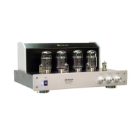
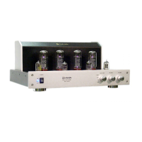
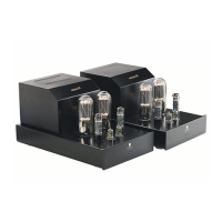
Because of its careful design and exacting standards of manufacture, your JD 502B amplifier should normally
require only minimal service to maintain its high level of performance.
CAUTION: The JD 502B amplifier contains sufficient levels of voltage and current to be lethal. Do not tamper with
a component or part inside the unit. Even with the power turned off, a charge remains in the energy storage
capacitors for some time. Refer any needed service to your authorized Jolida dealer or other qualified technician.
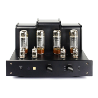
The vacuum tubes inside the JD 502B are high-quality 6550, 12AT7 and 12AX7 types. Replacement output tubes
should be matched for best sonic performance, although that is not a requirement for good sound. Reliable,
matched, low gas tubes¾such as those available from Jolida¾are strongly recommended for maximum
performance and longevity. Observe the operating and adjustment procedure for adjusting bias when replacing
any power output tubes.
Questions regarding your amplifier may be referred to the Customer Service Department of Jolida: (301) 953-
2014.
We hope you enjoy your musical experience.


 To Next Page
 Loading...