Grommet
Washer
CHAPTER I
CHARACTERISTICS
1.1 DESCRIPTION OF THE MACHINE AND ITS OPERATION.
MACHINE MODEL J-239 AUTOMATIC ELECTRONIC WITH TWO HOPPER BOXES FOR PLACING
GROMMET AND WASHER.
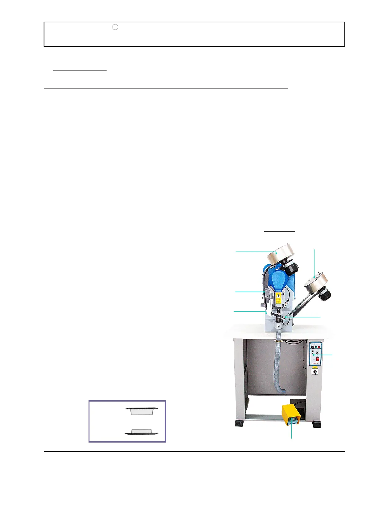
The machine consists of a metallic stand with a wood base on which the machine is mounted. The
pedal and the electronic equipment that control the machine are located in the stand.
The head of the machine is comprised of a machine housing and two raceways (one on each side).
The moving parts in the machine are located inside the housing, such as: the main motor, axles,
eccentrics, bearings, etc.; The grommets and the washers use the two raceways to descend.
The J-239 model is designed to automatically place the grommets with washers, the grommet without
the washer, or to punch holes in the material.
Facing the machine, the grommets are placed in the left hopper box “ ” and the washers in hopper
box “ ”. Both hopper boxes are rotated by individual 24 V motors.
The grommets that descend along the left raceway “ ” are held by a small finger, which stops them
from falling. Lower horizontal guides hold the washers descending along the right raceway “ ”.
A
B
A’
B’
The machine is controlled by an electronic unit
designated IMO V3 “ ”, located inside the mounting
stand.
The IMO V3 unit receives an electric signal through
pedal “ ” that allows the main motor “ ” located
behind the head, to quickly rotate and haul the
0
flywheel (part no. 274) with a belt making a 360
rotation causing the motor to stop sharply.
The flywheel (part no. 274) has a mainshaft (part no.
207) that joins the plunger with the other moving
0
parts. By rotating 360 , it exerts pressure on the
driving stem and therefore the grommeting action is
completed.
The top set spindle (part no. 218) inside the top set
(part no.217) inserts itself inside the grommet and
pulls it down from raceway “ ”. At the same time the
slide (part no. 297) pushes the washer from the slide
track and places it exactly on top of the bottom set
(part no. 219).
C
D E
A’
PAGE
3
R
MODEL J-239
JOPEVI
B
E
A
A’
C
D
B’
FIGURE 1