13
ENGLISH
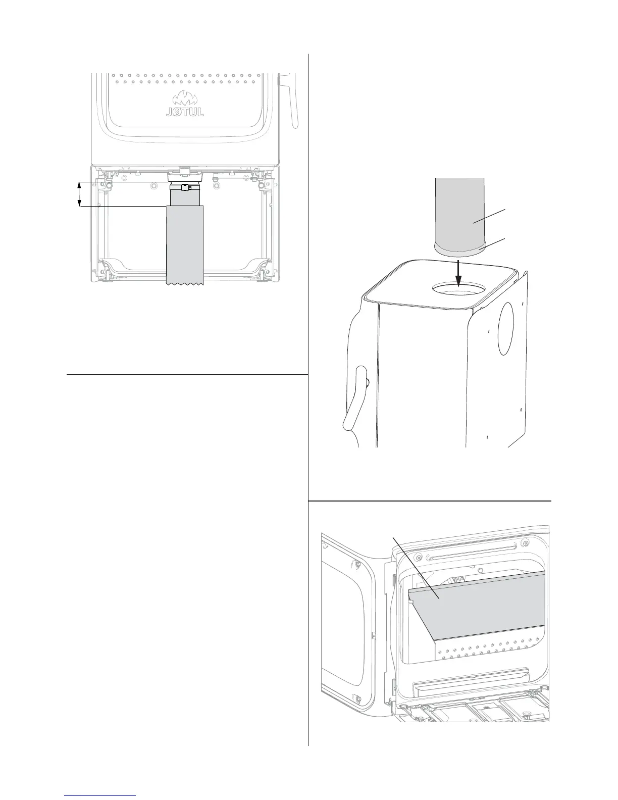
Fig. 17
100
4. See the installation instructions that follow with the external
air set.
5. Attach the hose to the external air connector with a hose
clip to avoid using joints. The external air hose insulation
ends approx. 100 mm below the burn chamber.
4.4 Chimney and fl ue pipe
• The fi replace must only be connected to a chimney and
fl ue pipe approved for solid fuel fi replaces with fl ue gas
temperatures as specifi ed in «2.0 Technical Data».
• The cross-section of the chimney must be designed to fi t
the fi replace. Use «2.0 Technical Data» to calculate the
correct chimney cross-section.
• The chimney must be connected in accordance with the
installation instructions of the chimney supplier.
• Before a hole is made in the chimney, the product should
be test-mounted in order to correctly mark the position of
the fi replace and the hole in the chimney. See fi g. 1 for
minimum dimensions.
• Make sure that the fl ue pipe rises all the way up to the
chimney.
• With a rear outlet, use a fl ue pipe bend with a sweep hatch
to allow sweeping.
• Please note that it is extremely important for connections
to have a degree of fl exibility. This is to prevent any
movement in the installation leading to the formation of
cracks.
• For recommended chimney draught, see «2.0 Technical
Data». For fl ue pipe dimension see “2.0 Technical Data”.
NB: The chimney’s diameter must be at least just as
big as the fl ue pipe.
NB! The minimum recommended chimney length is 3.5 m
from the fl ue pipe insert. If the draught is too strong, a fl ue
pipe damper can be installed and used to reduce the draught.
Protection grid for sweep ball
When a steel chimney is installed to the top outlet, a
protection grid for sweep ball must always be installed to
the top outlet (optional equipment).
4.5 Fitting a fl ue pipe with a top outlet
The product is supplied from the factory with the smoke outlet
fi tted for the top outlet.
Fig. 18
A
B
1. Thread the fl ue pipe (A) through the top plate and place it
in the top smoke outlet.
2. Seal well with a gasket (B).
Fig. 19
A
3. Place the baffl e (A) as displayed in the fi gure.
 Loading...