EasyManua.ls Logo

Joy-it DSO138-MINI - User Manual

Joy-it DSO138-MINI
15 pages
Print Icon
To Next Page IconTo Next Page
Loading...
DSO138-MINI
Mini digital oscilloscope
Joy-IT powered by SIMAC Electronics GmbH - Pascalstr. 8 - D-47506 Neukirchen-Vluyn - www.joy-it.net
Question and Answer IconNeed help?

Do you have a question about the Joy-it DSO138-MINI and is the answer not in the manual?

Summary

General Information

Device Overview and Specifications

Initial Setup and Connections

Connecting Power Supply

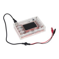
Connect the microUSB cable to the power supply input for device operation.

Connecting Test Leads

Connect the test lead to the signal input for measurements.

Using External Battery Option

Information on using a 3.7V lithium-ion battery for mobile use.

Device Configuration

Input Coupling Settings

Configure input coupling modes (DC, AC, GND) via the CPL switch.

Sensitivity Adjustment

Set vertical scale sensitivity using SEN1 switch (10mV, 0.1V, 1V).

Sensitivity Multiplier

Adjust signal amplification using SEN2 switch (X1, X2, X5).

Advanced Configuration Options

Display Mode Selection

Switch between Running and Hold measurement modes.

Timebase Settings

Configure horizontal resolution using SEL, '-', and '+' buttons.

Trigger Mode Configuration

Set trigger modes to Auto, Normal, or Single.

Edge Trigger Configuration

Select trigger event based on rising or falling signal edge.

Opening the Device for Maintenance

Accessing Internal Components

Remove rear screws to open the device housing.

Separating Motherboard and Display

Detach the motherboard from the display unit.

Display Unit Removal

Optional step to remove the display from the front case.

Connecting an External Battery Unit

Battery Unit Requirements

External battery needs charging or JYE118 module installation.

Connecting Battery to Mainboard

Steps to connect a 3.7V battery to the mainboard.

Battery Power Control

Use the Bat-Switch to control power from the connected battery.

Trimmer Calibration Procedure

Preparing for Calibration

Place display back on mainboard and connect test signal.

Initial Calibration Settings

Set SEN1, SEN2, CPL, and Timebase for initial calibration.

Adjusting Trimmer Capacitors

Calibrate C4 and C6 for accurate waveform display.

External Connections and Reset

External Trigger Connection

Connect an external trigger signal via the PB15 pin.

Device Reset Function

Reset the device by short-circuiting specific pins.

Additional Device Functions

Waveform Display Adjustments

Align vertical position and center horizontal display.

Waveform Management

Save and load waveform data from EEPROM.

Trigger Level and Signal Settings

Center trigger level and toggle test signal amplitude.

Waveform Data Transmission and Calibration

Send waveform data via serial port and calibrate analog gain.

Safety Instructions

General Safety Precautions

Handle device safely, use as intended, and check mains voltage.

Environmental and User Safety

Use in dry rooms, keep away from children, not a toy.

Voltage Measurement Limits

Suitable for extra-low voltages below 50V; avoid higher voltages.

Other Information and Support

Electrical Equipment Disposal

Information on ElektroG and symbol for proper disposal.

Product Return Options

Procedures for returning old appliances and packaging guidance.

Customer Support Channels

Contact options for assistance via email, ticket system, and phone.

Overview

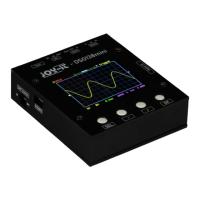
The Joy-IT DSO138-Mini is a compact digital storage oscilloscope designed for hobbyists and tinkerers, serving as an ideal complement to a multimeter. It offers the capability to measure and evaluate time-dependent signals without requiring expensive hardware. This device is an improved successor to the DSO-138 and can be used portably with an optionally available battery.

Function Description:

The DSO138-Mini provides all basic functions of a digital storage oscilloscope. It supports automatic and manual trigger modes, single-shot recording with signal analysis, and the restoration of stored signal waveforms. The device features a 2.4" TFT LCD with a resolution of 320x240 pixels for displaying waveforms and measurement values. Users can adjust various settings such as sensitivity, timebase, trigger mode, and trigger type to capture and analyze signals effectively. The device also allows for the display or hiding of measured values like frequency and voltage. For advanced use, it offers external trigger connection, reset functionality, and other optional connections.

Important Technical Specifications:

  • Number of channels: 1
  • Analog bandwidth: 0-200 kHz
  • Sensitivity range: 10 mV/div - 5 V/div
  • Sensitivity deviation: <5%
  • Resolution: 12 bit
  • Input impedance: 1 MΩ
  • Maximum input voltage: 50 Vpk
  • Coupling: DC, AC, GND
  • Max. real-time sampling rate: 1 MSa/s
  • Timebase: 10 µs/Div - 500 s/Div
  • Record length: 1024 Points
  • Trigger modes: Auto, Normal, Single
  • Trigger types: Rising/falling edge
  • Trigger position: 1/2
  • Display: 2.4" TFT LCD - 320x240
  • Voltage & power supply: 3.5 V - 6 V DC, 120 mA @ 5 V (via microUSB or external 3.7 V lithium-ion battery)

Usage Features:

The DSO138-Mini is straightforward to set up. It requires a microUSB cable for power, drawing approximately 120 mA at 5 V. A test lead is provided to connect to the signal input. For initial function checks, a 1 kHz test signal is output. The device starts automatically once power is supplied. Configuration options are accessed via buttons below the display: "SEL", "-", "+", and "OK".

  • Display Mode: Switch between "Running" (normal measuring) and "Hold" (pauses current measurement) using the "OK" key.
  • Timebase: Select the time base (ranging from 0.1 s to 10 µs) using the "SEL" key, then adjust with "-" and "+" keys. This controls horizontal resolution.
  • Trigger Mode: Choose between "Auto", "Normal", and "Single" modes. "Auto" records permanently, "Normal" holds if no trigger signal is present, and "Single" holds immediately upon trigger detection. Select with "SEL" and adjust with "-" and "+" keys.
  • Rising/Falling Edge: Trigger the measurement sequence by either a rising or falling edge. Select with "SEL" and adjust with "-" and "+" keys.
  • Show/Hide Measurement Values: Press and hold the "OK" key for three seconds to toggle the display of measured values like frequency or voltage.
  • Vertical Position Alignment: Move the cursor to the vertical position indicator via "SEL", then press and hold "OK" for three seconds and follow on-screen instructions.
  • Save Waveform: Simultaneously press "SEL" and "+" to store the current waveform in EEPROM, overwriting previous data.
  • Load Waveform: Simultaneously press "SEL" and "-" to load a previously stored waveform from EEPROM.
  • Center Horizontal Position: Move the cursor to the horizontal position indicator via "SEL", then hold "OK" for three seconds.
  • Center Trigger Level: Select the trigger level via "SEL", then hold "OK" for three seconds to automatically set it to the average signal amplitude.
  • Send Waveform: Press and hold "SEL" for three seconds to send waveform data in text form via serial port J5 (8N1 format, 115200 baud).
  • Toggle Test Signal Amplitude: Move the cursor to the rising/falling edge setting via "SEL", then hold "OK" for three seconds to set the test signal amplitude to 3.3 V or 0.14 V. The amplitude is indicated by a "♫" symbol.
  • Calibrate Analog Gain: Move the cursor to the trigger source setting (Int/Ext) via "SEL", then hold "OK" for three seconds to start calibration and follow on-screen instructions.

Maintenance Features:

The device can be opened for specific maintenance tasks, such as connecting an external battery, adjusting trimmers, or accessing optional connections.

  • Opening the Device: Remove the screws on the back of the device, then remove the cover and pull the motherboard off the display unit. The display unit can also be removed from the front by unscrewing it.
  • Connecting an External Battery: A 3.7 V lithium-ion battery can be connected to the mainboard as an alternative power source. If internal charging is desired, a JYE118 module must be installed. The "Bat-Switch" on the side controls power from the connected battery.
  • Trimmer Calibration: To calibrate the instrument, open the device to access the trimmer capacitors (C4 and C6). Connect the red test clamp to the test signal (black test clamp remains unconnected).
    • Set switch [SEN1] to 0.1 V and [SEN2] to X5. Set [CPL] to AC or DC. Set time base to 0.2 ms. Adjust trimmer capacitor C4 with a screwdriver until an even, rectangular waveform is displayed.
    • Set switch [SEN1] to 1 V and [SEN2] to X1. Repeat the adjustment procedure with capacitor C6. After calibration, the display unit and mainboard can be reassembled into the housing.

Safety Instructions:

Users must adhere to safety instructions to prevent injuries, electric shocks, heat generation, or fire. Keep the operating instructions and safety instructions in a safe place and hand them over if the device is passed to third parties. Use the device only for its intended application and according to instructions. Ensure the mains voltage matches the specified voltage before commissioning. The device is for use in dry rooms only and must not get wet or damp. It is not a toy and should be kept away from children. The device is only suitable for measuring extra-low voltages below 50 V and must not be connected to higher voltages.

Support:

Joy-IT provides support via e-mail (service@joy-it.net), a ticket system (http://support.joy-it.net), and phone (+49 (0)2845 98469 – 66, Mon-Fri 9 AM - 5 PM CET). Further information is available on their website: www.joy-it.net.

Joy-it DSO138-MINI Specifications

General IconGeneral
BrandJoy-it
ModelDSO138-MINI
CategoryTest Equipment
LanguageEnglish

Related product manuals