If necessary, the capacitor trimmers can be adjusted to calibrate the
instrument. To do this, rst, open the device as described in Chapter 5 -
Opening the device.
Aer you have removed both the mainboard and the display from the
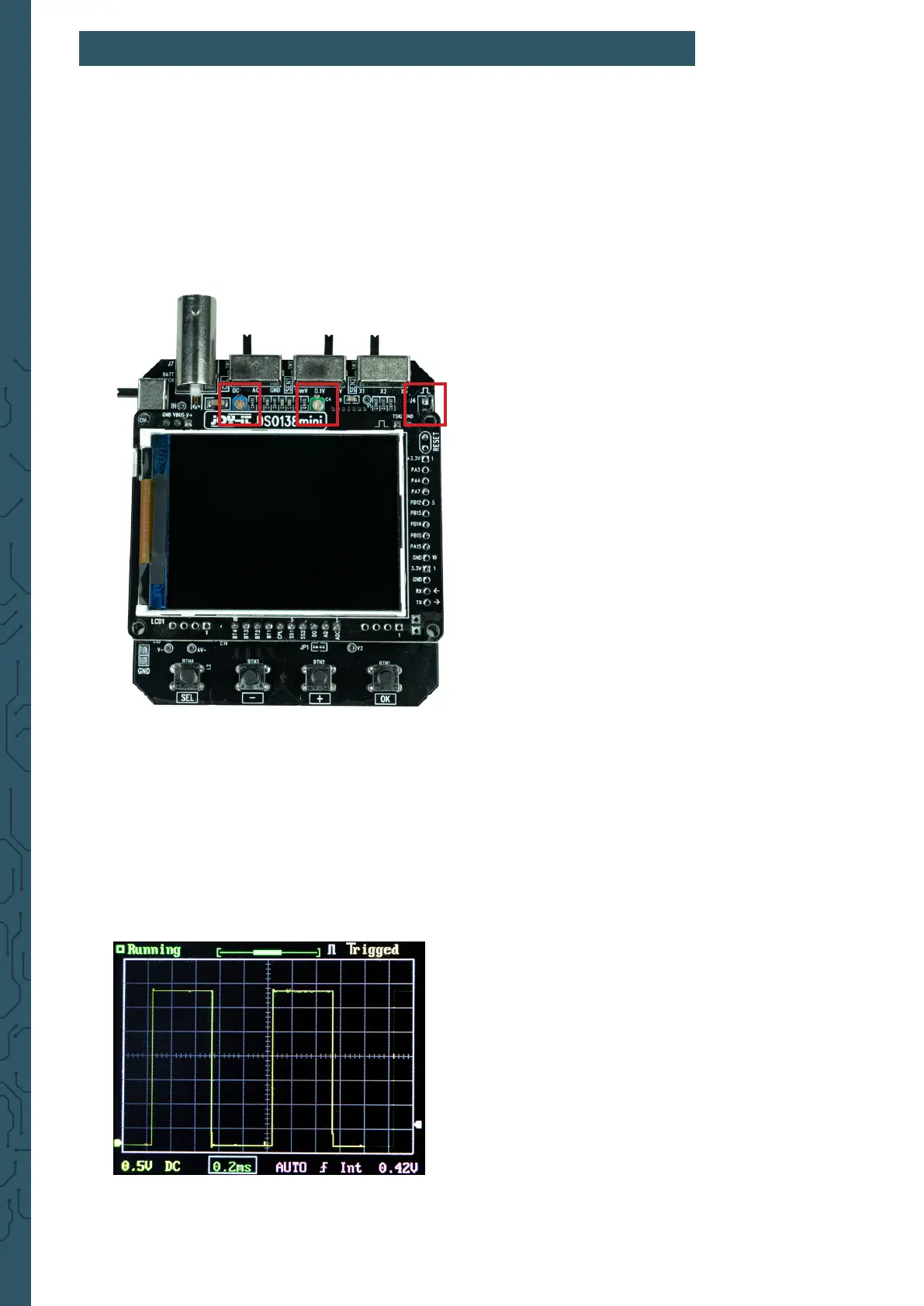
housing, you can rst place the display unit back on the mainboard. The
two trimmer capacitors are now freely accessible.
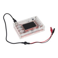
Now connect the lead to the connector of the device and connect the red
test clamp to the test signal. The black test clamp remains unconnected.
Now set the switch [SEN1] to 0.1 V and the switch [SEN2] to X5. The [CPL]
switch can be set to AC or DC.
Now set the time base to 0.2 ms. The test signal should now be displayed
similar to the following gure:
7. TRIMMER CALIBRATION
C6 C4
Testsignal