13
NEVER adjust any wiring or board setting while the gate is connected to power unless specically directed
otherwise. Disconnect the circuit from power, make your adjustment, and then restore power to test the
eect.
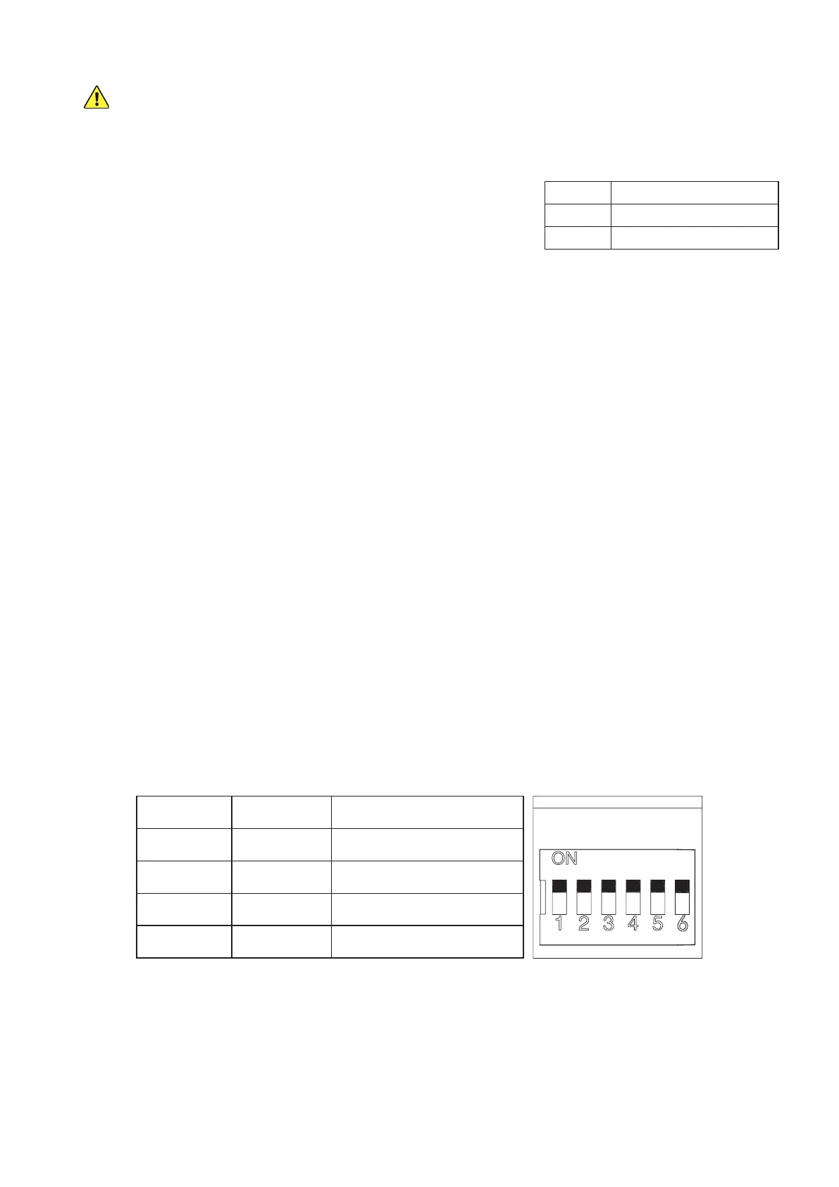
DIP2 Eect
UP Right Side Operation
DOWN Left Side Operation
Reversing Direction
The default placement for this system is on the right side of sliding gates
when looking out from the property. This is controlled by the up position
of DIP Switch 2. If you are installing your system on the left side of your
gate, make sure that this switch is ipped down away from the word ON
before connecting the gate to power.
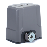
Changing Command Modes
The default command mode for this system is single-button operation. Pressing a single button on the remote
will cycle through the commands OPEN→STOP→CLOSE→STOP. This is controlled by the down position of DIP
Switch 6. If you prefer to use four separate buttons for the dierent commands, make sure that this switch is ipped
up towards the word ON before connecting the gate to power. Be aware that this setting makes accidents and
excessive wear from contradictory commands more likely and is not recommended.
Toggling the Movement Alarm
By default, the circuit board produces an alarm or buzzing noise when the motor is active. This is controlled by
the position of the small wire connecting Pins 1 and 2 on the Alarm Switch terminal. If you prefer to deactivate this
safety feature, move the wire to connect Pins 2 and 3 on the Alarm Switch terminal instead. Be aware that this can
make accidents more likely and is not recommended.
Activating Autoclose
By default, the gate remains open indenitely until it receives a command to close. This is controlled by the joint
down position of DIP Switches 3 and 4. To set the gate to close 12 seconds after reaching its maximum open
position, ip switch 4 up towards the word ON. To set the gate to close 24 seconds after reaching its maximum
open position, ip switch 3 up but leave switch 4 down. To set the gate to autoclose after 36 seconds, ip both
switches up. Because of the additional risk involved in the gate moving without direct instruction and supervision,
be sure that the gate’s obstruction sensitivity, stop speed, and similar setting are working as intended. Using the
movement alarm, infrared sensor, and other safety equipment is also highly recommended while autoclose is
active. (DIP Switch 5 can be ipped up to disable the automatic closure that occurs when a collision is detected, but
this is not recommended for most users.)
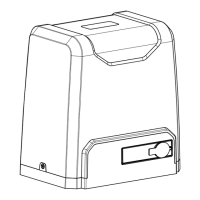
DIP3 DIP4 Eect
UP UP 36 Second Delay
UP DOWN 24 Second Delay
DOWN UP 12 Second Delay
DOWN DOWN Manual Closure
Adjusting the Gate’s Sensitivity
The leftmost adjustment knob VR1 controls obstruction sensitivity. The far left position is the most sensitive to any
obstruction but may cause overreaction, e.g., to strong winds or leaves along the gate’s track. Moderate settings
are ne for most users, but careful trial and error can nd the ideal settings for your situation.