14
Adjusting the Gate’s Forcefulness
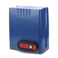
Various settings control the forcefulness of the gate. The gate normally minimises wear by speeding up gradually as
it begins moving. DIP Switch 1 can be ipped up to deactivate this soft start. (This can damage the system and is
not usually recommended.) Similarly, the rightmost adjustment knob VR4 controls the gate’s initial force. The far left
position minimises wear on the motor and gate but may cause it to react too sluggishly. The 2nd knob VR2 controls
the braking force of the motor. Again, the far left position minimises wear on the motor and gate but may react too
slowly to obstructions and limit switches, causing a forceful collision with the end stops and brackets. The 3rd knob
VR3 controls the sensitivity to the limit switches. The far left position responds immediately and disables any soft
stop, but this can cause unnecessary wear and even cause your gate to stop before reaching its end bracket.
Remote Pairing
The top button of both included remotes (C) should come already paired with your gate opener. Up to 38 additional
remotes or wireless control buttons can be paired to the gate’s circuit board. Be sure that they use the 433.92 MHz
(LPD433 Channel 35) radio band or can be congured to do so.
NEVER pair the same button to 2 dierent gates or devices at the same time.
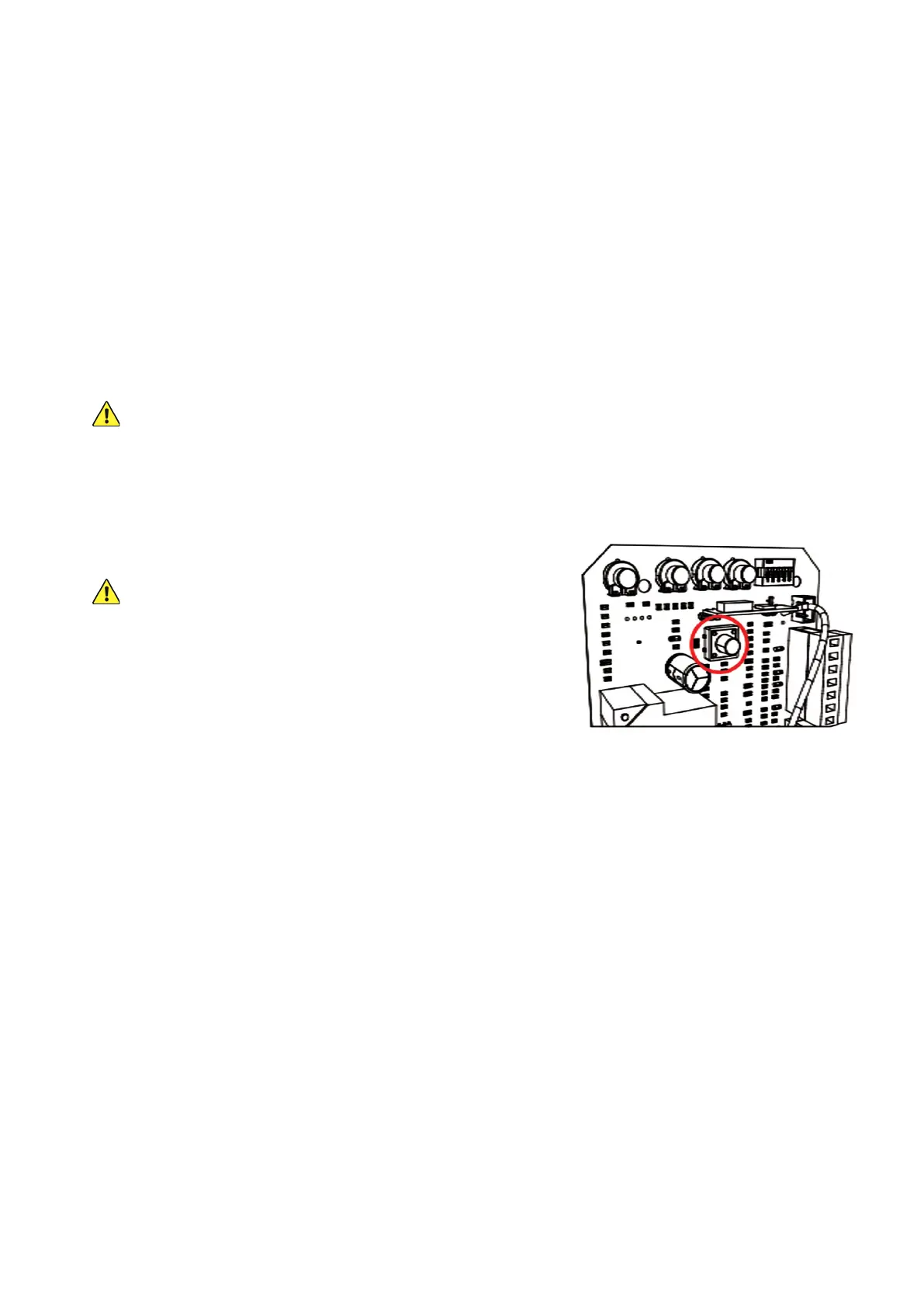
1. Remote pairing must be done with the circuit board exposed and connected to power. Be careful and only touch
the pairing button while the circuit is live. Disconnect the motor’s power while its casing is being removed and
replaced or making any other adjustment besides remote pairing.
2. Press the remote pairing button long enough for the nearby
indicator light to come on.
DO NOT hold the button down, as this has a dierent eect.
3. Press the remote button to be paired or enter a passcode and
press the open button on your wireless control.
4. Press the same button on the remote again or reenter the
passcode and press the open button again on the wireless
control. The remote indicator light should ash and then go out.
5. The button or keypad is now paired and can be used to open or close the gate. This pairing should remain
stored in memory even when power to the gate opener is cut accidentally or at its circuit breaker.
6. Test that your gate responds correctly to commands from the new remote or keypad. When you are nished
pairing and testing, disconnect the gate from power, replace the motor’s covers and fasteners, and restore
power.
Unpairing Remotes
This board cannot unpair an individual remote. If you need to remove lost remotes from the system’s memory,
you will need to delete ALL stored remotes at once. Open the motor and circuit board casing as before, press and
HOLD the pairing button, and wait for the indicator light to come on and then turn o. Use any remote to test that all
stored remotes have been purged.
Once this process is successful, pair the remotes that you want to continue using in the same way as before.