PRINCIPLE OF MUL TIPLEXED LAMPSYSTEM
In order that the component count may be reduced, J.P.M. have decided to adopt a system of MULTIPLEXING
for lamps. MPS2 therefore has the capacity to display 256 lamps or a combination of lamps and segments.
This is achieved via a 16 x 16 matrix.
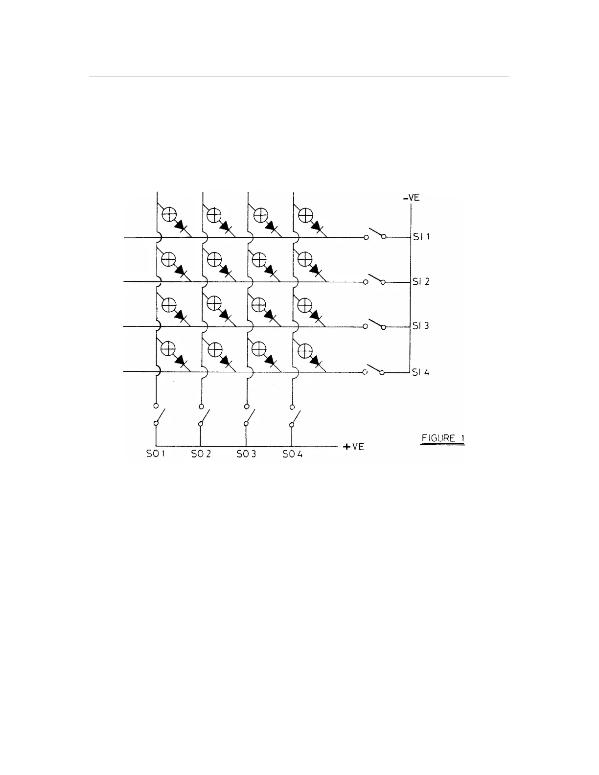
To simplify matters. Figure 1 demonstrates the principle with a 4 x 4 matrix. In this example, 16 lamps can be
controlled by only 8 transistors (shown as switches). Each lamp therefore is under control of two specific
switches. Diodes are also fitted to prevent backfeeds.
By turning on a column (So1 -So4) and by setting up data on a row (Si1 -Si4), up to 4 lamps may be turned on.
After a period of say 1 msec, the column address set up on So1 -So4 is incremented and the data on Si1 -Si4 is
changed, a second row of 4 lamps may be displayed. By incrementing the column address at a rate greater than
70Hz the lamps will appear to be continuously lit with little suggestion of flickering. Since the lamps are 12v
devices and are being switched in a 1/16 duty cycle, the supply voltage is raised to 50v DC to overcome the
reduction in effective brightness.
As long as the computer is running the 50v will be shared between the lamps as is explained above. However,
should the computer cease to run then it is theoretically possible for the lamps to burn very brightly, however a
safeguard is built in, whereby should the computer fail, then the lamps will extinguish.