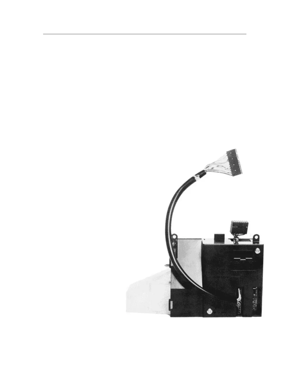
MS126 SEPARATOR
This separator is attached via two self tapping screws to the MS111 and is interconnected electrically.
The MS126 is a fully active 4 way separator unit. Two solenoids can be operated which in turn operate three
routing paddles.
In order to enable the -VE common output, a loom is connected between the MS111 and connector 4 of the
separator.
Coin Routing
The MS126 has four coin exits from the separator unit. The routing of coins to different exits is programmed by
an MS126 routing plug. The routing plug is a 14 way polarised connector which is inserted into the separator.
The wire links within the routing plug complete the electrical circuit between the MS111 and the solenoid drive
circuitry. See MS126 Routing Configuration tor further intormation.
CONNECTOR 3: 1 - Coin output common (-12V). 8 -Inhibit 1Op.
2 - Coin output £1.00. 9- Logic & solenoid supply + 12V .
3 - Polarising. 10 -Common OV.
4 - Coin output 50p. 11 -Inhibit 20p.
5 - Coin output 20p. 12 -Inhibit 50p.
6 - Polarising. 13 -Inhibit £1.00.
7 - Coin output 10p.
Supply Voltage
+12V DC +/- 10%.
Quiescent current 25mA maximum.
Current during coin flight 55mA maximum.
Current During Solenoid Operation
Diverted coins: 2.25A maximum for 0.58 seconds maximum.
Non-diverted coins: 0.75A for 0.25 seconds maximum.
Negative common supply +0V to -13.5V maximum.