MPS2 INSTALLATION PROCEDURE
Installation Procedure
1. Ensure that all plugs and sockets are engaged, also that all earth connections are secure.
2. Connect to mains supply and switch on at the transformer assembly.
3. During power up, a tone will sound and the power on reset LED on the main board will illuminate for
approximately 3 seconds then extinguish.
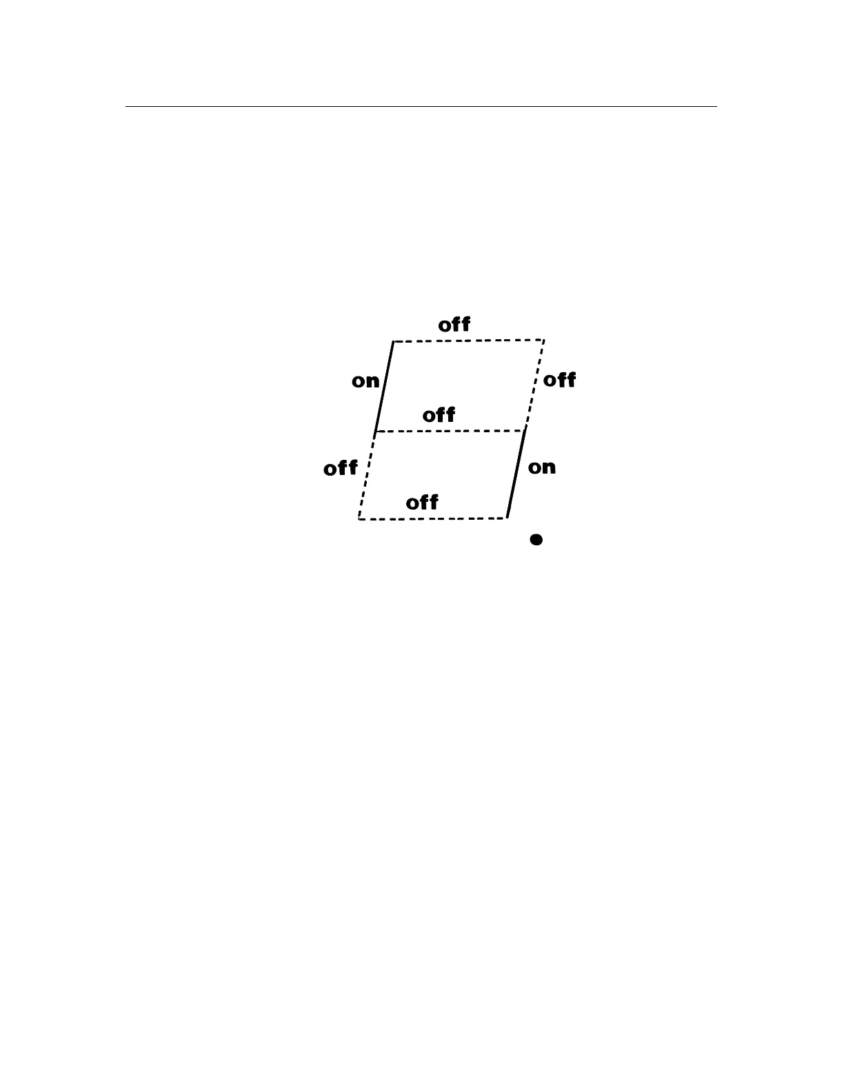
4. For correct operation, the following segments of diagnostic LED 5 will illuminate.
The power supply LED's 1 -3 (+5v, +12v, -12v) should also be illuminated.
5. After the initial reel spin you may proceed with the self test routine as detailed in the personality package.
The function of each individual segment is as follows:
TOP UART2 TX ON = Transmit Data.
TOP LEFT I/O Enable ON = Enable.
TOP RIGHT UART2 RX ON = Receive Data.
CENTRE NM1 ON = Interrupt State.
BOTTOM LEFT Reel Drive Enable OFF = Enable.
BOTTOM RIGHT MUX Timeout OFF = Timeout.
BOTTOM Peripheral Communication ON = Transit Data.
DECIMAL POINT Not Used
Mains Input
The mains transformer has the facility to be operated from 200v, 220v or 240v AC input. This is achieved via a
plug fitted to the exterior of the chassis. The plug is polarised and can in no way be inserted incorrectly. For
connector details see label on power supply chassis.