Do you have a question about the JPT LP Series and is the answer not in the manual?
Essential safety instructions including power supply connection, laser cover, and eye protection.
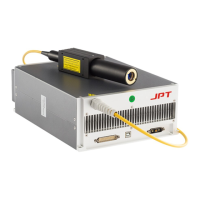
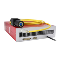
Overview of the JPT E type fiber laser for marking applications, highlighting speed, precision, and compact size.
Details the items included in the YDFLP package, such as the laser, test sheet, and precautions.
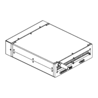
Detailed dimensions and diagrams for the YDFLP-E-20&30-LP-S laser module.
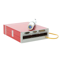
Provides dimensions for the standard isolated output head of the YDFLP-E-20-LP-S model.
Details the dimensions for the standard isolated output head of the YDFLP-E-30-LP-S.
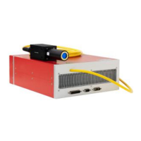
Details dimensions for the output head of the YDFLP-E-50-LP-L model.
Details the 24V DC power supply connection, including cable diagram and pin definition.
Describes the RS-232 connector for PC or red card connection, with pin definitions.
Explains the DB25 interface for marking control system connection and its pin definitions.
Details the DB25 control for output power and sequence timing diagrams.
Guide to connecting the GUI software, including serial COM port selection and state.
Explains GUI control modes like Full Ctrl, Free Ctrl, and MO signal control for laser emission.
Covers default parameter settings and selection for Lock PRR, Default pulse, Simmer, and Red Power.
Monitors laser running status via indicator lights and provides descriptions for alarms like Board tempLT, PRE lowE.
Details specific alarm conditions including temperature errors, voltage errors, and seed source issues.
| Brand | JPT |
|---|---|
| Model | LP Series |
| Category | Measuring Instruments |
| Language | English |