Do you have a question about the JPT YDFLP-E-80&100-M7-M-R and is the answer not in the manual?
Provides a general description of the YDFLP E-M7 Series fiber laser.
Details the items included in the YDFLP fiber laser package.
Outlines crucial operating conditions and safety protocols for the laser.
Explains the nomenclature used for YDFLP fiber laser models.
Lists the key technical parameters and performance data of the laser.
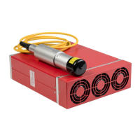
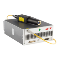
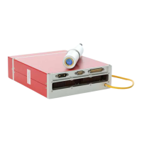
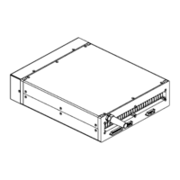
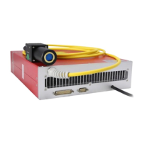
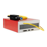
Provides physical dimensions and mounting information for the laser module.
Describes the power supply connector and wiring for the laser.
Details the RS-232 interface for laser control and communication.
Explains the DB25 connector for system control and interface.
Guides on installing and operating the JPT GUI software for laser control.
Covers monitoring laser status, parameters, and understanding alarm conditions.
The JPT YDFLP-E-80&100-M7-M-R is a pulsed fiber laser designed for high-speed and precise marking applications. This device is controlled via a standard DB25 interface and powered by a 48V DC supply. Its compact size makes it ideal for integration into small marking systems, offering improved pulse response and overall performance compared to similar products.
The core function of the YDFLP-E-80&100-M7-M-R is to generate pulsed laser light, specifically invisible 1064nm wavelength radiation, with an average output power exceeding 60W (for the E-80 model) or 100W (for the E-100 model) and peak power over 10kW. This Class 4 laser is capable of producing a variety of waveforms, including CW (Continuous Wave) and pulsed outputs with durations ranging from 2ns to 500ns. The laser's output power is controlled via TTL signals through pins 1-8 of the DB25 interface, allowing for a range of 0-100% output power, encoded from 0-255. The actual output power is influenced by the frequency setting.
The device incorporates a built-in red pilot laser, which can be enabled or disabled, and its brightness can be adjusted. This feature is useful for alignment and targeting without emitting the main high-power laser. The laser also includes a comprehensive monitoring system accessible via GUI software, allowing users to track operational parameters and alarm conditions.
To ensure safe and optimal operation, several usage features are highlighted. The laser requires a stable 48V DC power supply, with specific connections for main power (laser pump) and control circuit power. The power interface utilizes a DB-7W2 plug (male) with clearly defined pin assignments for +48VDC, -48VDC, and ground. The control interface is a DB25 connector, which is typically used to connect to a marking control system. This interface provides signals for power control (IPO-IP7), warning signals, emission modulation (PA), frequency modulation (TTL), and an emergency stop function.
The laser's pulse width can be adjusted through a serial input via pins 2, 3, and 22 of the DB25 connector. This allows for precise control over the laser's pulse characteristics, with instructions transmitted in binary form. The Pin22 signal acts as an enable for pulse width adjustment, requiring activation 10us in advance of sending serial data.
For monitoring and control, the JPT GUI Laser Testing Software (TypeE) is provided. This software offers multiple functions, including laser control, setting default parameters, selecting control modes, alarm monitoring, and internal parameter monitoring. The GUI allows users to connect to the laser via an RS-232 connector (USB to RS232 cable required) and manage various settings.
The GUI offers different control modes:
Default parameter settings can be modified and saved via the GUI, including:
The manual emphasizes several maintenance and safety features to ensure the longevity and safe operation of the device. Proper connection of the 48V DC power supply is crucial to prevent damage. Maintaining a bending diameter of the fiber cable larger than 15cm is essential to avoid power decrease or laser damage. Adequate ventilation is required, with a minimum of 10cm air gaps around the fiber laser and consistent airflow direction to prevent temperature rises. The recommended operating temperature range is 0-40°C for normal mode and 5-35°C for performance mode. Good heat dissipation is vital for prolonging the laser's working life.
The use of fused silica lenses is recommended over ordinary K9 glass optical lenses in medium to high power applications to prevent issues like focus drift, spot size inconsistency, or light output instability due to the "thermal lens effect." Keeping the laser output window clean and covered when exposed to the environment is critical, as dust can cause heat, damage the lens, and decrease output power.
Safety precautions include ensuring the power is off before installation or uninstallation, and always wearing appropriate laser safety goggles (OD4+ or better) when the laser is powered on, as both direct and reflected beams can cause permanent damage to eyes and skin, and may cause fire. Even at 0% power emitting, the average output laser power is around 100mW.
The laser system incorporates self-locking mechanisms. If abnormal conditions occur (e.g., frequency signal < 1kHz, high temperature, low power supply), the system will stop working to protect itself. A restart and power-on are required to resume operation.
The GUI software provides extensive monitoring capabilities, including:
Alarm conditions are clearly described, with some alarms (like temperature alarms for sensor1 and sensor2) being self-recovering once conditions return to normal, though re-emission signals are required. Other alarms (e.g., PRE lowE, Voltage error, No pulseE, Seed TEC) require a laser restart to clear the alarm state. The flashing red indicator light provides a direct visual cue for various alarm conditions, such as short flashing for Sensor1 alarm, long flashing for Sensor2 alarm, and specific patterns for other critical issues.
| Laser Type | Fiber Laser |
|---|---|
| Model | YDFLP-E-80&100-M7-M-R |
| Wavelength | 1064 nm |
| Average Power | 80W/100W |
| Operating Voltage | 220 VAC, 50/60 Hz |