YDFLP-E-80&100-M7-M-R User Manual
14
File Number: JG-MCYF-SM-0039
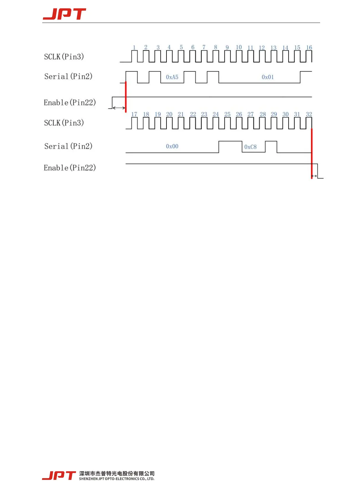
Figure 11 Diagram of 200ns Pulse Width Control Sequence
T1: the duration is 10us, and the enabling signal of pulse width adjustment needs to be turned on
10us in advance before adjusting the serial input and the serial clock signal.
T2: the duration is 10us. After pulse width adjustment, it needs to delay 10us before closing.
If the user sets 350ns pulse width, the input instruction is: 0xa5 → 0x01 → 0x01 → 0x5e,
where 0x01 and 0x5e represent the pulse width value 350.
The parameter of this instruction is the binary value of pulse width.
The user can compile any pulse width, but the laser only accepts the specified pulse width
(refer to the specifications of various versions for specific pulse width). If the given pulse
width is out of the range, the laser will output with the close pulse width value.
3. JPT GUI Laser Testing Software-TypeE
TypeE is designed for YDFLP-E series laser. It has multiple functions including laser
control, setting the default parameters, setting the control mode, alarm monitoring, DB25
interface monitoring, internal parameters monitoring etc. Using the matched GUI software for
JPT laser is recommended. The GUI software, in addition to set the parameters, also can be used
for signal monitoring and troubleshooting etc.
 Loading...