EasyManuals Logo

JPT YDFLP-E-80&100-M7-M-R User Manual

JPT YDFLP-E-80&100-M7-M-R
29 pages
To Next Page IconTo Next Page
To Previous Page IconTo Previous Page
Page #13 background imageLoading...
Page #13 background image
YDFLP-E-80&100-M7-M-R User Manual
9
File Number: JG-MCYF-SM-0039
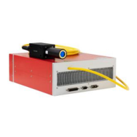
2.2 RS-232 Control Connector
RS-232 connector is available for connecting PC or the Red Control card. Customer can
monitor and control laser by GUI software, serial commands or red card after connected. Pins
definition is shown in below Figure8 & Table 7:
Figure 8 RS232 Connector DB9
Table 7 RS-232 Interface Definition
PIN#
Description
146-9
No need to connect
2
RxD
3
TxD
5
GND
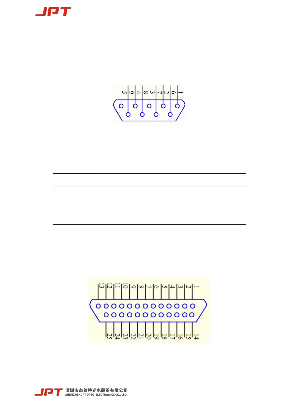
2.3 DB25 Control Connector
DB25 is the interface usually used to connect the marking control system. The Pins are
defined as shown in Figure9 and Table 8.
Figure 9 DB25 Connector

Questions and Answers:

Question and Answer IconNeed help?

Do you have a question about the JPT YDFLP-E-80&100-M7-M-R and is the answer not in the manual?

JPT YDFLP-E-80&100-M7-M-R Specifications

General IconGeneral
BrandJPT
ModelYDFLP-E-80&100-M7-M-R
CategoryMeasuring Instruments
LanguageEnglish

Related product manuals