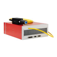
YDFLP-E-80&100-M7-M-R User Manual
10
File Number: JG-MCYF-SM-0039
Table 8 DB25 Interface Definition
Latches power setting of the laser, effective during rising edge(This feature
can be enabled in the GUI)
GND
Description: PIN10-15 have connected to the ground inside the fiber laser,
only need to connect control card GND with one of the Pins.
Warning signal
Description:16 low level,21 high level: Normal
16 low level,21 low level: temperature alarm
Emission Modulation input (PA)
HIGH= Emission ON
LOW=Emission OFF
Frequency Modulation (TTL)
Emergency Stop signal
High level: Normal; Low level: Emergency Stop (this function can be
selected in GUI)
Emergency stop signal is from low to high, need to detect the rising edge
of MO firstly, then the laser can be re-emitted.
Red beam ENABLE (Red Beam is preferred when Laser and Red Beam
are mutually exclusive. * refer to note2)
Pulse width adjustment ENABLE (Please refer to the following pulse
width control section for specific control mode).
High Level: Red Beam On
Low Level: Red Beam Off
MO signal for turn on/off
HIGH: ON
LOW: OFF
Note 1: 4.6-5.4V will be recognized as TTL high; 0-0.5V will be recognized as TTL low.
Note 2: The default setting is red beam preferred. Red beam Pin22 signal has higher priority than
MO and PA signal. When Pin22 signal is high, MO and PA signal will be shut down internally.
The laser can be emitted by restarting MO and PA after Pin22 signal is low. Priority mode can be
set up in GUI (please refer to Chapter 3.1.2).

 Loading...