EasyManuals Logo

JPT YDFLP-E-80&100-M7-M-R User Manual

JPT YDFLP-E-80&100-M7-M-R
29 pages
To Next Page IconTo Next Page
To Previous Page IconTo Previous Page
Page #15 background imageLoading...
Page #15 background image
YDFLP-E-80&100-M7-M-R User Manual
11
File Number: JG-MCYF-SM-0039
PIN 1~8 Output Power Control
PIN1~8 controls the output laser power by TTL signal. The encoding can be set within the
range of 0~255, which is corresponding to the 0~100% output power. The actual output laser
power may not be a linear relationship with these settings. And the actual output power also
related to the frequency. Please refer to the example of current setting in Table 9:
Table 9 Current Setting (example)
Setting 1
Setting 2
Setting 3
Setting 4
PIN 1
0
0
0
0
PIN 2
0
0
0
0
PIN 3
0
0
0
0
PIN 4
0
0
0
0
PIN 5
0
0
0
1
PIN 6
0
0
1
1
PIN 7
0
1
1
1
PIN 8
1
1
1
1
Current
~50 %
~75 %
~87.5 %
~93.75%
PIN 18-20 DB25 Sequence
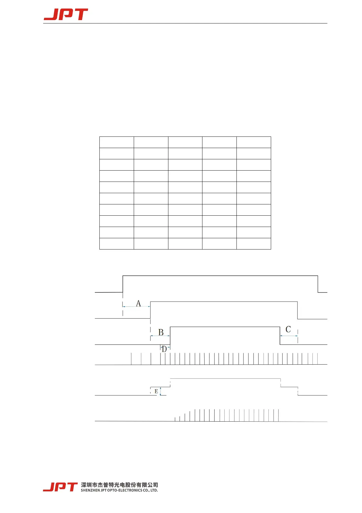
Figure 10 Diagram of DB25 Control Time Sequence
A: 12 seconds System initialization time.
B:
4ms MO and PA signal delay time.
C: Switching off PA should be earlier than MO or at the same time.
SUPPLY VOLTAGE 48V
PIN18 MO
PIN19 PA
PIN20 PRR
PUMP CURRENT
LASER OUTPUT

Questions and Answers:

Question and Answer IconNeed help?

Do you have a question about the JPT YDFLP-E-80&100-M7-M-R and is the answer not in the manual?

JPT YDFLP-E-80&100-M7-M-R Specifications

General IconGeneral
BrandJPT
ModelYDFLP-E-80&100-M7-M-R
CategoryMeasuring Instruments
LanguageEnglish

Related product manuals