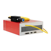
YDFLP-E-80&100-M7-M-R User Manual
8
File Number: JG-MCYF-SM-0039
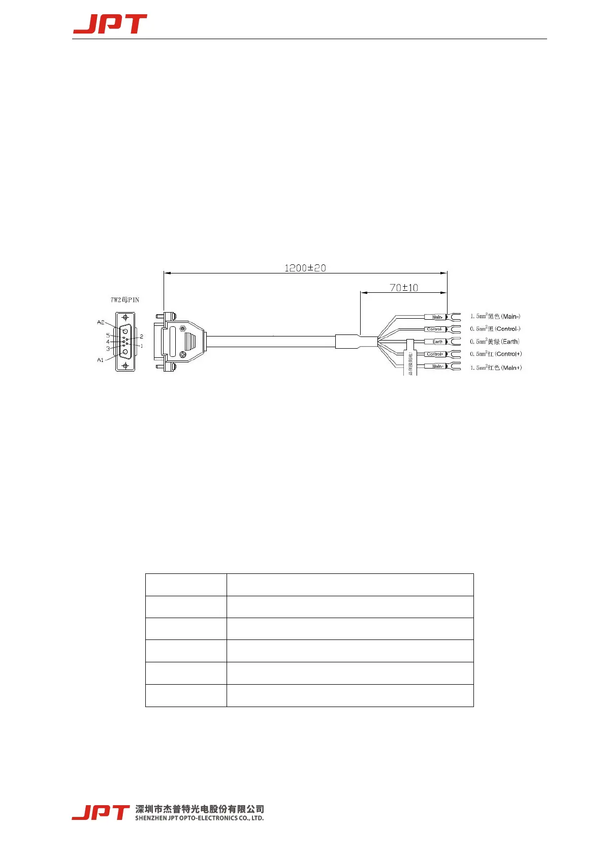
2. Laser Interface
2.1 Power Supply Connector
Please refer to Figure7 & Table 6 in below to install the power cable to the 48V DC power
supply, and ensure the DC power supply can provide sufficient output power. Please also note
the polarity of the cable when connecting. The “main+” and “control+” at the end of the power
cable are 48V DC positive, “main-” and “control-” are 48V DC negative, “Earth” is the ground
wire.
Figure 7 Diagram of the power supply cable
"Main +" and "Main -" are power supply pins of laser pump, "Control +" and "Control -"
are power supply pins of control circuit. If independent power supply function is not required,
main and control power cable can be used in parallel.
The power interface of the laser is DB-7W2 plug (male), and the pin distribution is as follows:
Table 6 Definition of power supply cable
+48VDC,laser pump power supply
+48VDC,control circuit power supply
Note: Housekeeping (main and control power supply independent) function can be customized.
 Loading...