Do you have a question about the JPT YDFLP-E-20-M7-S-R and is the answer not in the manual?
Essential safety measures for operating the laser device.
Details on safety labels and their placement on the device.
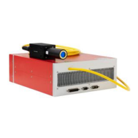
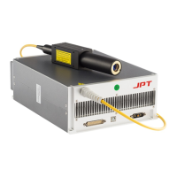
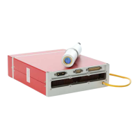
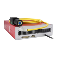
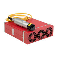
Overview of the JPT M7 Series fiber laser features and applications.
Items included in the product packaging.
Guidelines for safe operation and environmental conditions.
Identifies the product as Ytterbium Doped Fiber Laser Pulse (YDFLP).
Specifies the product type within the series.
Indicates the average output power rating.
Describes the pulse characteristics of the laser.
Details the attributes of the optical fiber used.
Lists any additional functions of the product.
Displays output waveforms for pulse widths from 2ns to 45ns.
Displays output waveforms for pulse widths from 60ns to 500ns.
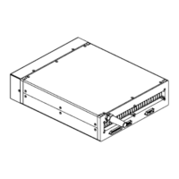
Mechanical dimensions of the laser module and output head.
Details about the power supply cable and its connection.
Information on the RS232 serial connector and its pin definition.
Details on the DB25 control interface for system connection.
Overview of the GUI software and its connection methods.
Explains how to use the GUI for controlling laser functions.
Enables full control of laser parameters via GUI.
Allows independent control of specific laser parameters.
Locks the laser to the GUI setting frequency.
Sets the default pulse width when no control command is received.
Controls the height of the first pulse.
Overview of laser status monitoring parameters and alarms.
Alarm for optical circuit temperature exceeding set range.
Alarm for circuit temperature exceeding set range.
Alarm for abnormal low primary current.
Alarm for abnormal seed source temperature.
Alarm for no seed source backlight or signal frequency.
Alarm for voltage supply being too low or too high.
Monitors status of DB25 signals (PA, MO, D0-D7).
Monitors laser power, temperature, pulse width, and frequency.
The JPT YDFLP-E-20/30-M7 Pulsed Fiber Laser is a Class 4 laser module designed for high-speed and precise marking applications. It emits invisible 1064nm wavelength laser radiation and is intended as a component for incorporation into a larger laser product, requiring additional features for laser safety and compliance with 21 CFR1040.10.
The YDFLP-E-20/30-M7 is a Ytterbium Doped Fiber Laser Pulse (YDFLP) that offers adjustable pulse width (M series) or fixed pulse width (LP series). It is controlled via a standard DB25 interface and powered by a 24V DC supply. The device's pulse response and performance are noted to be superior to similar products, making it ideal for compact marking systems.
The laser features a GUI (Graphical User Interface) software, TypeE, which provides comprehensive control and monitoring capabilities. This includes setting default parameters, selecting control modes (GUI Full Control Mode or Free Control Mode), alarm monitoring, DB25 interface monitoring, and internal parameter monitoring. The software also records error events that can lead to system self-locking.
The YDFLP-E-20/30-M7 series includes two main models: YDFLP-E-20-M7-S-R and YDFLP-E-30-M7-S-R.
The device also specifies cut-off frequencies for different pulse widths. For laser safety and long lifetime, when the pulse width is set to ≥80ns, the frequency range is limited to 400kHz. The laser will operate at its expected output power above the cut-off frequency, but power will drop below it to maintain peak power.
| Brand | JPT |
|---|---|
| Model | YDFLP-E-20-M7-S-R |
| Category | Measuring Instruments |
| Language | English |