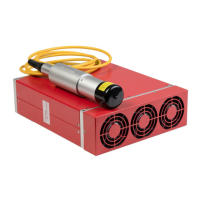
YDFLP-E-20/30-M7 User Manual
File Number: J-SI-0036
3.2 RS232 Connector
Figure 8 RS232 connector-DB9
Table 6 RS-232 Interface Definition
3.3 Control Interface
DB25 behind the power module is the interface used to connect the control system (such as
marking machines) to the laser system. Please make sure that the interface is connected firmly
before the operation.
The PIN is defined as shown in Figure 9 and Table 7.
Figure 9 DB25 Interface
Table 7 DB25 interface definition
Signal of power save, (this function is available in GUI) Rising

 Loading...