2.Installation of Scanner Unit > 2.4 PRECAUTIONS
2-36
2.4.2 Routing coaxial cable and flexible wave guide
In the case of the three-unit system consisting of the display unit,
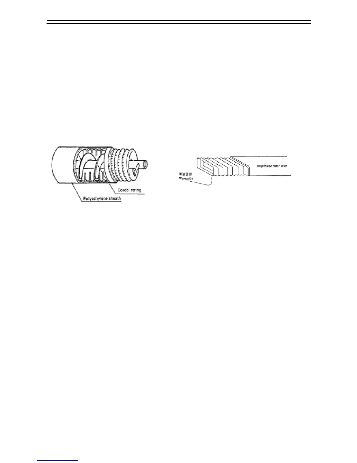
transmitter-receiver, and the scanner, use a Coaxial cable, shown in Fig 2-9
Coaxial cable, between the transmitter-receiver and the scanner for the S-band,
and use a Flexible wave guide, shown in Fig 2-10 Flexible wave guide, for the
X-band.
1) Protecting coaxial cable and flexible wave guide
• Since cables and wave guides are hollow inside, when mounting them by using electric
wire bands, try not to fasten the bands too tightly around the cables and wave guides.
If they are fastened too tightly, the inside will become deformed or blocked, which may
cause the receiving sensitivity to decrease or the transmitter-receiver to be damaged.
Fig 2-9 Coaxial cable
Fig 2-10 Flexible wave guide
• Stabilize the coaxial cable and the flexible wave guide by supporting members that are at maximum
intervals of 1000 millimeters. Mount a supporting member for the horizontal wiring portion on the
compass deck at an angle of 300 to 400 millimeters, and put a protective metal cover over the cable
and wave guide.

 Loading...


