Do you have a question about the JRC JFE-680 and is the answer not in the manual?
Explains pictograms used in the manual and on equipment for safety.
Describes warning labels affixed to the echo sounder body regarding high voltage.
Details safety warnings for operating the echo sounder, including electrical shock and damage prevention.
Provides cautions for electrical installation, operating temperatures, unstable surfaces, and cold environments.
Describes the primary functions including depth alert, power fail alert, and data output.
Lists key features like display modes, memory, and dual frequency, and notes IMO performance standard compliance.
Lists standard equipment including the main unit, matching box, and transducer.
Details optional components like secondary matching boxes, transducers, and mounting kits.
Provides external dimensions for the JFE-680 recorder unit and its matching box.
Details mounting dimensions for NKF-341/NKF-345 and NKF-392C transducers.
Illustrates installation diagrams for NKF-393, NKF-394, and NKF-396 transducers.
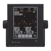
Explains the real-time echo sounding display in standard mode, including dual frequency.
Describes the history mode for displaying past 12-hour or 24-hour depth graphs and sounding data.
Details the docking mode for displaying depth data, often used in port operations.
Covers turning the unit on/off and adjusting control panel and screen brightness.
Explains how to control the depth range and adjust the sensitivity (gain) for optimal readings.
Provides details on setting sensitivity, including effects of low/high sensitivity and proper settings.
Details how to select display modes and change screen colors for day/night visibility.
Guides on accessing menus, selecting items, and registering settings using ENT and CLR keys.
Explains how to cancel menus, use the print function, and stop audible alerts.
Describes how to move the depth and position cursors in different display modes.
Details cursor movement in history mode and adjusting screen brightness.
Outlines the menu structure for display settings like scroll speed, gain, range, and alert configurations.
Details menu options for printer control, communication settings, and maintenance functions.
Covers settings for image scrolling speed, clutter, and noise suppression for clearer display.
Explains interference rejection settings and how to configure auto gain and auto range.
Details how to set FWD/AFT draft and configure the cursor display method.
Explains how to select the cursor display method, including OFF, ON, and AUTO modes.
Describes settings for key acknowledgement buzzer and relay contact output modes.
Details how to set depth alarms, including enabling/disabling and setting the alarm depth threshold.
Covers configuration for system alerts related to depth loss and transmitter abnormalities.
Covers configuration for system alerts related to receiving signal, bubbles, and printer status.
Lists various alert types, their screen display icons, and associated descriptions.
Explains the general state transitions of alerts and the color conventions used for alarms and warnings.
Guides on setting memory length for history mode and configuring day/night display colors.
Covers setting depth display modes and configuring primary/secondary transducer frequencies and positions.
Details how to configure transducer frequency and installation position for primary and secondary units.
Details settings for STC curves, inner hull offsets, and keel correction values.
Explains how to adjust date, time, time difference, and configure GPS synchronization.
Covers enabling/disabling the print function and selecting print modes like copy, history, or log.
Shows examples of print modes and context for PRINTER port output.
Provides detailed explanations for History and Log print modes, including graphical output.
Details settings for automatic log book printing intervals and log output length.
Explains settings for transfer speed (baud rate) and selecting the printer model.
Configures depth data output formats (Ver1.5, Ver2.3, ALL) and alert output settings.
Details specific NMEA 0183 data output formats for depth, alerts, and system information.
Explains the structure of various alert message formats, including time, ID, status, and checksums.
Provides details on message structures like SDALC, SDARC, ACN, and SDHBT for communication and alerts.
Manages whether maintenance system information is outputted via the depth output port.
Determines if printer control signals or maintenance system information is sent to the printer port.
Provides general cautions related to equipment installation, such as grounding and avoiding water exposure.
Guides on flush-mounting the recorder unit, including dimensional details.
Provides instructions for wall-mounting the recorder unit, with dimensional specifications.
Details the installation process and parts list for the NKF-341 transducer.
Details the installation process and parts list for the NKF-345 transducer.
Details the installation process and parts list for the NKF-392C transducer.
Details the installation process and parts list for the NKF-393 transducer.
Details the installation process and parts list for the NKF-394 transducer.
Details the installation process and parts list for the NKF-396 transducer.
Illustrates the wiring and connection of various components, including transducers and power supplies.
Guides on performing self-tests for control unit, LCD, key unit, printer, and alert system.
Details self-test procedures for the control unit and LCD unit, including error indicators.
Covers self-test procedures for the key unit, printer functionality, and alert system tests.
Covers procedures for displaying, outputting, and deleting recorded alert histories.
Explains how to execute line monitor, display RX monitor, and view system numbers.
Outlines procedures for requesting service, warranty terms, and out-of-warranty repair policies.
Specifies the warranty period, keeping period of maintenance parts, and repair conditions.
Provides guidance on disposing of the equipment in accordance with local regulations.
Illustrates and explains different types of noise like bubble noise and interference noise.
Explains how seabed composition affects the recording quality and appearance.
Describes how abrupt slopes and side lobes can cause difficult readings and false echoes.
Discusses challenges in displaying echoes from abrupt slopes and rugged surfaces.
| Brand | JRC |
|---|---|
| Model | JFE-680 |
| Category | Marine Equipment |
| Language | English |