Do you have a question about the JRC JLN-720 and is the answer not in the manual?
Details hazards and precautions for high voltage components within the equipment.
Steps to take when a person receives an electric shock, including first aid.
Provides procedures for first-aid treatment in emergencies, including CPR.
Explains the meaning of various symbols used in the manual and on the equipment.
Critical warnings about severe hazards and potential fatalities from improper use.
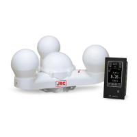
Describes the functions of the JLN-720 satellite log equipment.
Lists the key features and capabilities of the equipment.
Details standard and optional components included with the system.
Provides outline drawings and dimensions of system components.
Shows the overall connection diagram of the satellite log system.
Explains the main display unit and its functions and operations.
Describes the optional remote displays and their functions.
Details the Multi-Information Display (MID) and its operations.
Explains the Wing Display unit and its buttons.
Describes the Distance Counter and its trip reset function.
Covers powering the unit ON/OFF and adjusting display brightness.
Explains how to view ship speed, rate of turn, and distance data.
Details how alerts are displayed and their meaning.
Accessing and navigating the main menu system for equipment settings.
Explains common buttons used across menus for saving, resetting, and navigating.
Covers touch calibration, ROT scale, brightness, equipment info, speed digits/units.
Settings for GPS accuracy, satellites, smoothing, SBAS, and alerts.
Settings for remote displays including date, mode, and speed selection.
Guidelines for installing main display and processor units.
Instructions for installing the GPS compass sensor.
Illustrates the system's overall electrical connections.
Outlines regular maintenance tasks for the equipment.
Provides steps for addressing equipment issues and abnormalities.
Information on how to request repairs for the equipment.
Suggests specialized inspection and maintenance services.
Guidelines for disposing of the equipment and its battery according to regulations.
Lists general technical specifications of the satellite log system.
Provides detailed specifications for the GPS compass sensor.
Details specifications for the distribution processor unit.
Lists specifications for the main display unit.
Provides specifications for the optional remote display NWZ-650SDR.
Details specifications for the optional remote display NWZ-840SDR.
Lists specifications for the optional Multi-Information Display.
Explains input and output data formats for the system.
Shows installation drawings for the GPS compass sensor.
Provides installation drawings for the distribution processor.
Installation drawings for the main display unit.
Installation drawings for the optional NWZ-650SDR remote display.
Installation drawings for the optional NWZ-840SDR remote display.
Installation drawings for the optional MID NWZ-4610.
Installation drawings for the optional Wing Display NWW-61T.
Installation drawings for the optional Digital Display NWW-62TB.
Installation drawings for the optional Distance Counter NWW-7.
Installation drawings for the optional Analog Display NWW-24.
Installation drawings for the optional Analog Display NWW-25.
Installation drawings for the optional Analog Display NWW-26.
Installation drawings for the optional Junction Box NQE-7720.
Installation drawings for the optional Dimmer Unit NCM-227.
Installation drawings for the optional Dimmer Unit NCM-329.