JMA-9100/7100 Installation Manual > 2.INSTALLATION OF SCANNER UNIT > 2.1 EQUIPMENT CABLE
2-5
2
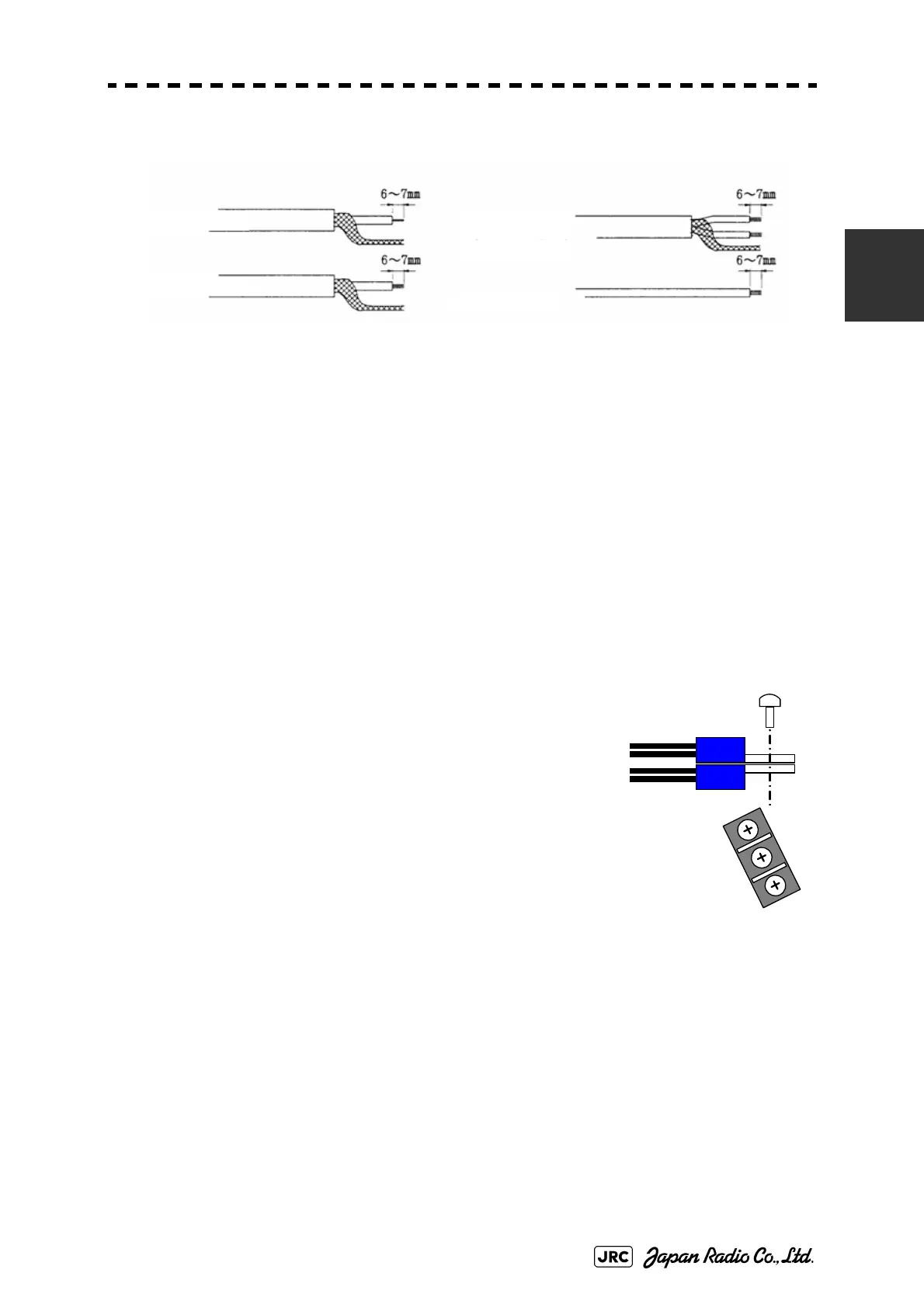
Process each cable end according to the procedures shown below.
Fig 2-6: CFQ-6912 End processing of each wire
Twist each pair of the following colored wires and clamp them to the crimp-type
terminal. (V2-M4 recommended)
• RED.T/GRN.T →+terminal
• WHT.T/ORN.T →+terminal
• PUR.T/BRN.T →-terminal
• BLU.T/GRY.T →-terminal
Overlay those wires as shown in the drawingat the
right, and fix them onto the CBD-1684A (TB522) or
TB401 terminal block.
Twist each pair of the following colored wires and
connect them to the TB4101 of the terminal board
circuit CQD-2097.
• YEL.T/PNK.T →TB4101(+48V)
• BLK.T/SKY.T →TB4101(+48VG)
Shield Cable
Shield Cable
(twisted pair)
Coaxial Cable
Vinyl Cable
Fig 2-7: Fixing onto the
terminal block
 Loading...


