JMA-9100/7100 Installation Manual > 2.INSTALLATION OF SCANNER UNIT > 2.4 PRECAUTIONS
2-33
2
the convenience of the service staff who take care of installation, maintenance,
adjustment, and repair of the scanner by providing adequate footholds to the mounting
rack and the radar mast.
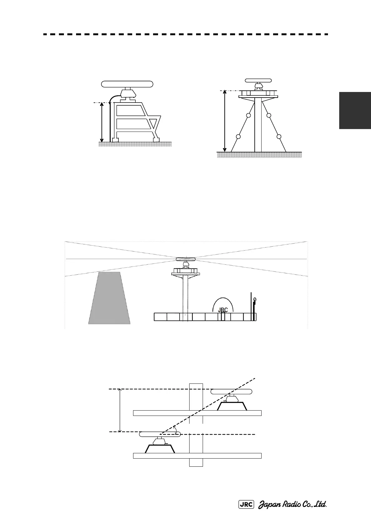
Fig 2-24: Mounting rack and mast for the scanner
• When installing the scanner, select a location where there are the fewest structural
objects in the surrounding area so that false echos which interfere with target detection
will not be generated by signal reflection from other scanners, deck structures, and
cargo. Only as a guide, note that structural objects should not exist within the range of
the vertical beam width (Fig 2-25).
Vertical beam width of X-band: Approx. 20 ( 10.0 when the height of the radiating section is 0 )
Vertical beam width of S-band: Approx. 25 ( 12.5 when the height of the radiating section is 0 )
Fig 2-25: Scanner and the surrounding structural objects
• When installing two or more scanners, scanners in close proximity should have a
minimum vertical elevation separation angle of 20 and a minimum vertical separation of
1m where possible, so that those scanners do not enter each other's vertical beam width
range.
Fig 2-26: Scanners in close proximity
Installation
Height
Installation
Height
ビーム幅
Beam width
1m (min)
20°(min)
 Loading...


