INTRODUCTION
This manual describes
the
basic
operating principles
of the
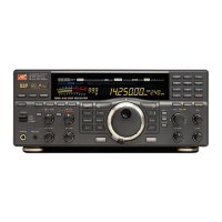
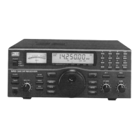
NRD-545DSP receiver
and
items required
for its
maintenance. Please refer
to the
User Manual supplied with
the
equipment
for how to
operate
and
handle
the
NRD-545.
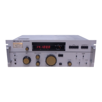
The
NRD-545 consists
of
eight units. Each circuit
has
been designed
to
minimize
the
number
of
locations that
might require adjustment with
the
passage
of
time,
and so
increase operating stability.
It is
therefore only necessary
to
service
the
equipment according
to the
instructions contained
in
this manual when
a
fault
becomes apparent.
Please refer
to the
table
of
units
and be
sure
to
enter
the
name
and
type
on the
form when ordering replacement
unit.
Please
refer
to the
parts lists
and
enter
the
unit
type, part
No.,
type,
and
code when ordering parts.
CONTENTS
1.
SPECIFICATIONS
1
2.
FRO
NT
PANEL
AND
REAR PANEL
3
2-1
FRONT PANEL
3
2-2
REAR PANEL
4
3.
LAYOUT
OF
UNITS
5
4.
ASSEMBLY DRAWING
6
5.
BLOCK
DIAGRAM
7
6.
DESCRIPTION
OF
CIRCUITS
8
6-1
OUTLINE
OF
BLOCKS
8
6-2
DESCRIPTION
OF
UNITS
9
7.
ADJUSTMENT
15
7-1
PREPARATION
15
7-2
CBD-1363
POWER CIRCUIT
16
7-3
CDE-860
DISPLAY
UNIT
17
7-4
CGK-160
REF/DDS
UNIT
19
7-5
CGA-184
LOOP1 UNIT
20
7-6
CDA-752
DSP
JJNIT
21
7-7
CFH-71
1ST
IF
UNIT
22
7-8
CFL-356
RF
TUNE UNIT
25
7-9
INTEGRATED ADJUSTMENTS
26
7-10
CHE-199
WIDEBAND CONVERTER UNIT
34
8.
TROUBLESHOOTING
41
8-1
SIMPLE PROBLEMS
41
8-2
MORE SERIOUS PROBLEMS
42
8-3
MAINTENANCE
43
9.
CIRCUIT DIAGRAM
AND PCB
LAYOUT
44
9-1
CIRCUIT DIAGRAM
44
9-2 PCB
LAYOUT
56