All operating elements and connections described
can be found on the fold-out page 3.
1 Operating Elements and Connections
1.1 Controller CS-1CU (upper side)
1 Speaker
2 Headphone output as a 3.5 mm jack; if a plug is
connected to this jack, the speaker (1) will be
switched off
3 Volume control for the headphone jack (2) and
the speaker (1)
4 Control (rotary switch with 11 positions) for the
volume of all speakers and the maximum volume of
all headphones on the controller and on all micro-
phone stations
5 Display
6 Button to start and stop the stopwatch feature
in the setting menu:
to select the operating mode
and to change a setting
7 Button to reset the stopwatch feature (when
counting is stopped)
in the setting menu:
to select the operating mode
and to change a setting
8 Button SET
short actuation: to switch over between the indica-
tion of date/time and the stopwatch mode;
longer actuation (approx. 2 seconds) to activate the
setting menu
in the setting menu:
to confirm a menu item selected
or a setting
9 POWER switch
1.2 Controller CS-1CU (rear side)
10 Mains switch for connection to a mains socket
(230 V~/ 50 Hz) via the cable provided
11 Support for the mains fuse;
replace a fuse that has blown by one of the same
type only
12 Selector switch to route the audio signals via a
unit for signal processing connected (e. g. equal-
izer) to the jacks “Insertion” (14)
position “I”: unit inserted into the signal path
position “O”: unit not inserted into the signal path
13 RCA jacks “Telephone” with input (in) and output
(out) to connect a telephone system via a tele-
phone coupler
14 RCA jacks “Insertion” with input (in) and output
(out) to insert a unit for external signal processing
(e. g. equalizer) into the signal path
15 RCA jacks “Recorder” with input (in) and output
(out) to connect a recorder; the jacks are available
for the left (L) channel and right (R) channel
respectively of a stereo recorder; however, signal
processing in the conference system will be mono-
phonic
16 RCA jacks “Line” with input (in) to connect a signal
source with line output level and output (out) to
connect an amplifier system
17 Control “ Gain” to adjust the input amplification
for the inputs “Recorder in” (15)
18 Control “ Gain” to adjust the input amplification for
the microphone input (20)
19 Jacks “Trunk in/out” 1 and 2 to connect the micro-
phone stations; each of the two jacks will allow con-
nection of a chain of up to 25 microphone stations
CS-1CH and/or CS-1DU
20 Microphone input as an XLR jack; the input will
supply a phantom power of 12 V; therefore, con-
nect microphones with balanced output only!
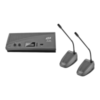
1.3 Microphone station CS-1CH (CS-1DU)
Figure 3 shows the microphone station CS-1CH (for
the chairperson); deviations from the microphone sta-
tion CS-1DU (for delegates) are described in the cor-
responding operating elements.
21 Microphone
22 Ring; will light up when the microphone is switched
on or when a system test is performed (
chapter
5.7)
23 LED; will light up when the microphone is switched
on or when a system test is performed (
chapter
5.7)
24 Two 3.5 mm jacks to connect headphones; if a plug
is connected to one of these jacks, the speaker (25)
will be switched off
25 Speaker
26
for CS-1CH only:
Priority button for the chairperson
to interrupt a discussion between delegates
27 Talk button to switch on/off the microphone
28 Jack to connect the next microphone station
29 Plug for connection to one of the jacks “Trunk
in/out” (19) on the controller or to the jack (28) of
another microphone station
30 Volume control for the headphone outputs (24)
31 Control GAIN to adjust the microphone amplifica-
tion
32
for CS-1CH only:
Switch for the automatic acoustic
signal which will sound when an announcement is
interrupted; the acoustic signal will be audible
when the switch is in the upper position
33
for CS-1CH only:
Switch to define the behaviour
after interrupting an announcement
lower position: microphones of stations which had
been switched on before the interruption will be auto-
matically switched on again after the interruption
upper position: after an interruption, the micro-
phones of all delegate stations will remain switched
off
10
ENGLISH