– 2 –
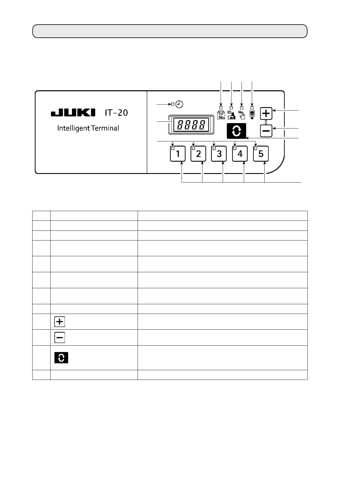
4. CONFIGURATION
No. Switch/indication Description
A
Clock LED Lights up when the clock is displayed.
B
7-segment indication block Indicates various ID data and clock information.
C
Product No. LED
Lights up when Product No. ID is displayed on
B
.
→
See
“5-1. (1) Normal startup mode screen”
.
D
Operator ID LED
Lights up when Operator ID is displayed on
B
.
→
See
“5-1. (1) Normal startup mode screen”
.
E
Optional ID LED
Lights up when Optional ID is displayed on
B
.
→
See
“5-1. (1) Normal startup mode screen”
.
F
Transmitted data LED
Lights up when Transmitted data is displayed on
B
.
→
See
“5-1. (1) Normal startup mode screen”
.
G
No. LED The selected No. will light up.
1
switch
The value to be indicated in
B
is set up here. The value in-
creases when this switch is pressed.
2
switch
The value to be indicated in
B
is set up here. The value de-
creases when this switch is pressed.
3
switch
The item to be indicated in
B
is changed here. The indicated
item changes when this switch is pressed.
→
See
“5-1. Normal startup mode”
.
4
No. switch Setup information (ID) registered for each item is selected here.
1
A
4
C
2
D E F
3
B
G