− 46 −
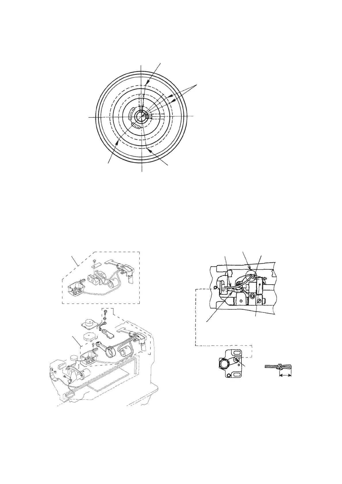
7. ENGRAVED MARKER DOTS ON THE HANDWHEEL
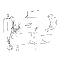
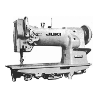
8. LUBRICATION ROUTE DIAGRAM
Range of needle-up stop position (white)
Needle-up stop position at the time of
reverse revolution to lift needle
Adjustment of thread trimmer cam (red)
Needle-down stop position
LS-1342/42-7
LS-1340/41
1 Tie oil wicks in oil tank as shown in the illustration above.
2 Oil wick (to hook driving shaft front bushing)
3 Oil wick ((to vertical feed rod)
Tie the end of oil wick as shown in the illustration above.
4 Tube and oil wick (to hook shaft saddle)
Tie the end of oil wick in oil tank as shown in the illustration
above.
5 Vertical feed rod felt
6 Enter oil wick under hook shaft saddle felt.
(Upper side lubrication route)
(Lower side lubrication route)
1
2
3
4
5
6
20