−50 −
Explanation of input changeover jumper switch
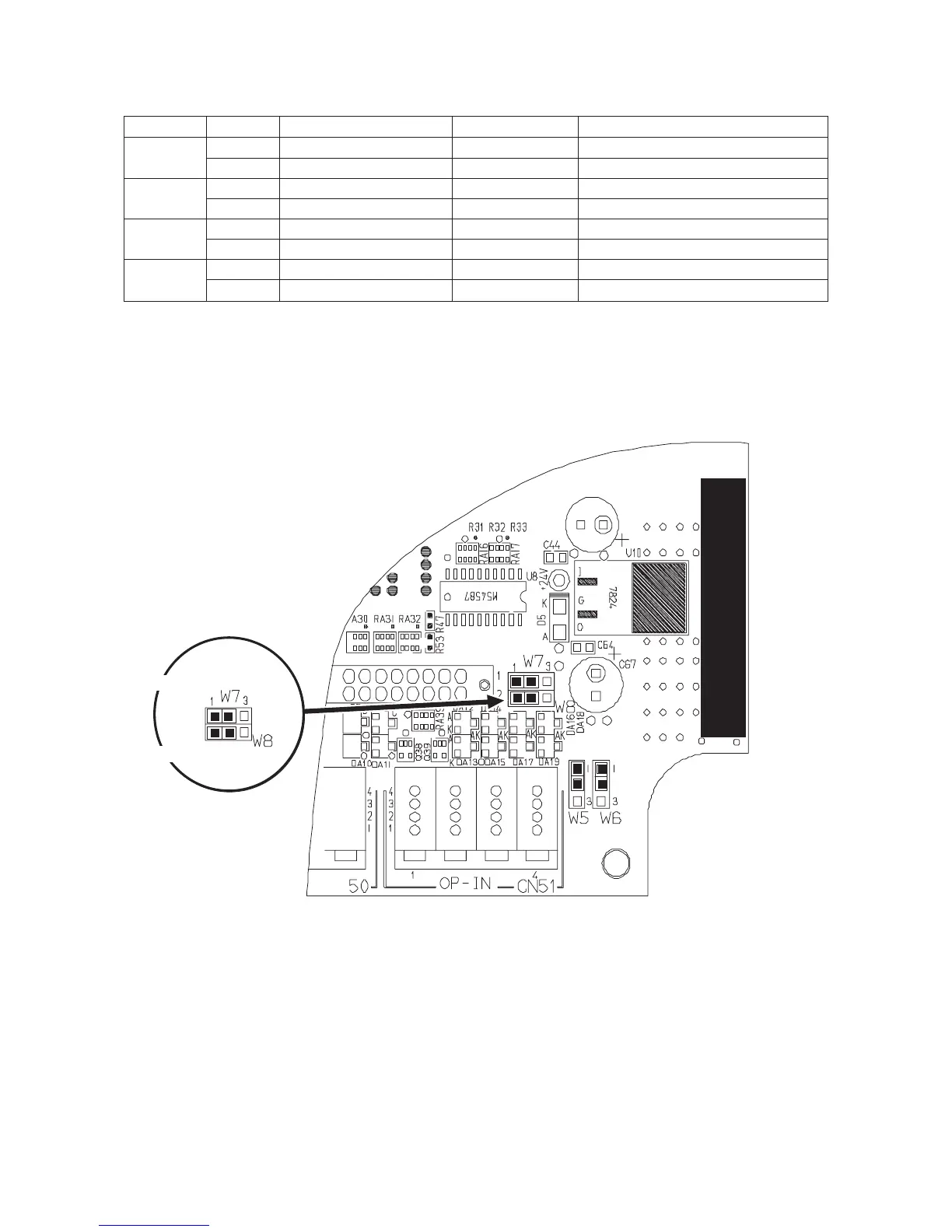
It is possible to change 4 inputs among the optional inputs by changing the setting of jumpers W5 to W8.
Jumper No. Pin No. Signal Input connector Remarks
W5 1-2 Digital input of +5V CN51-4 3Pin
2-3 Analog input of +5V (1) CN51-4 3Pin
This input becomes analog signal input. (Caution 1.)
W6 1-2 Digital input of +5V CN51-4 4Pin
2-3 Analog input of +5V (2) CN51-4 4Pin
This input becomes analog signal input. (Caution 1.)
W7 1-2 Digital input of +5V CN51-3 2Pin
2-3 Digital input of +5V CN36 3Pin
W8 1-2 Digital input of +5V CN36 3Pin
2-3 Digital input of +5V CN42 2Pin
(Caution) 1. For the analog input, it cannot be used with the user's setting such as simplified program,
memory switch, etc.
Position of optional input changeover jumper wire and pin arrangement
Pin No. 1 2 3
Pin No. 1 2 3

 Loading...


