20
FIG. 28
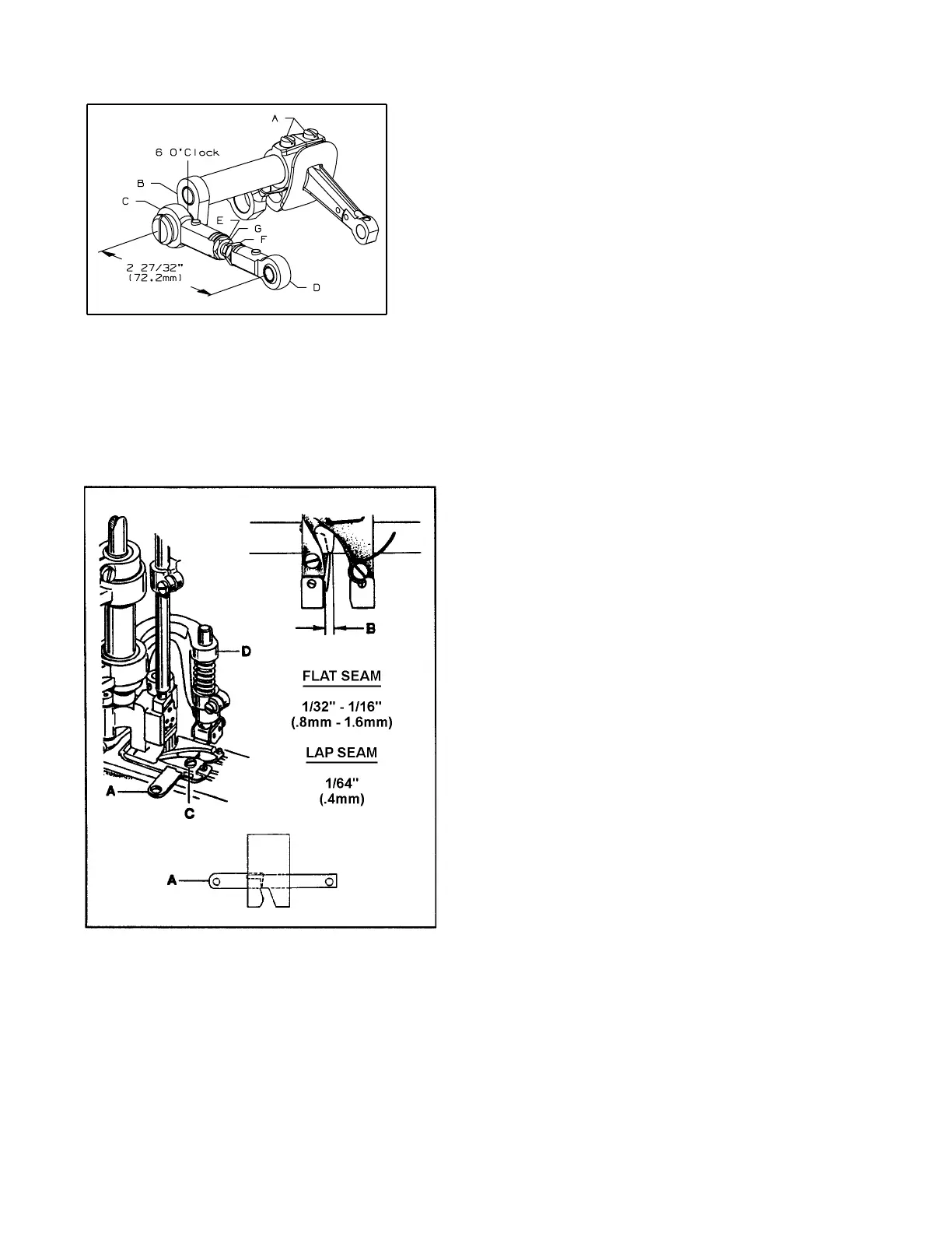
FIG. 29
SETTING THE KNIFE DRIVE LEVER (CONT.)
At this time the knife drive lever should be in the 6 o'clock
position. If adjustment is necessary, loosen screws (A, Fig. 28)
in the needle lever and reposition knife drive lever (B) to the
6 o'clock position. Tighten screws (A). The dimension be-
tween the centerline of right and left knife drive connection
ball joints (C and D) must be 2 27/32" (72.2mm). Loosen left
hand thread nut (E), right hand thread nut (F) and turn con-
necting rod (G) until dimension is achieved. Tighten nuts (E
and F).
SETTING THE TRIMMING KNIVES FOR FLAT SEAMING
(STYLES 36200L100-52, L100-60, T300-52, T300-60, U300-52, U300-60)
To make the adjustments for a flat seam, position lower
knife (A, Fig. 29) in the foot so it extends 1/32" to 1/16"
(0.8mm to 1.6mm) past the right side of the left toe (B)
(approximately between the second and third needles).
Loosen screw (C) and move knife in or out as required.
Tighten screw (C) securely.
SETTING THE TRIMMING KNIVES
FOR LAP SEAMING
(STYLES 36200L100-52, L100-60, L200-52, L200-60,
L202-52, L202-60, L210-52, L210-60, U300-52,
U300-60)
To make the adjustments for a lap seam, position lower
knife (A, Fig. 29) in the foot so it extends 1/64" (0.4mm)
past the right side of the left toe (B) (approximately even
with the first needle). Loosen screw (C) and move knife
in or out as required. Tighten screw (C) securely.
(ALL STYLES )
Turn handwheel in operating direction until knife driving
bracket (D) is positioned to the extreme left. At this time
the front edge of both knives should be parallel with
each other and the upper knife cutting edge should
overlap lower knife cutting edge by 1/64" (0.4mm)
 Loading...