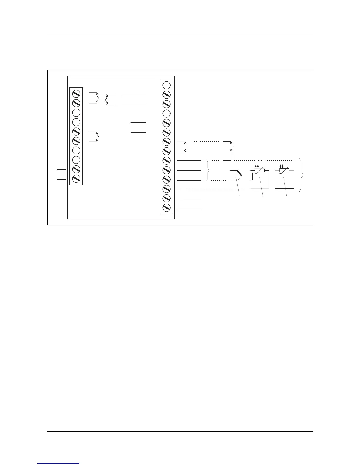
19
3 Electrical connection
3.4 Connection diagram 702072, 702074
(1) Output 1 (K1):
Relay 230V AC/3A
(2) Output 2 (K2):
Relay 230V AC/3A
(3) Output 3 (K3): Logic 0/14V (4) Output 4 (K4) (option):
Analog output or
Relay 230V AC/3A
(5.1) Binary input 1
(for potential-free contact)
(5.2) Binary input 2 (for potential-free
contact); (alternative to input
0/2…10V, configurable with
setup program)
(6) Analog input
(6.1) Standard signals
(input 0/2…10V alternative to
binary input 2)
(6.2) Thermocouple
(6.3) RTD temperature probe
(3 wire)
(6.4) RTD temperature probe
(2 wire)
(7) RS485 interface
(Option)
(8) Voltage supply
110-240V AC
(Option: 20-30V AC/DC)
1
2
5
6
N(L-)
L1(L+)
12
15
16
17
20
21
22
23
AC/
DC
19
18
24
(1)
(2)
(8)
(5.1)
RxD/TxD
+
-
0/4—20mA
-
+
0/2—10V
+
(7)
(6)
-
+
(6.1)
(6.2) (6.3) (6.4)
+
-
(3)
0/4—20mA
0/2—10V
+
-
(4)
0/14V
13
(5.2)