Do you have a question about the JUMO cTRON 04 and is the answer not in the manual?
Specifies installation environment requirements and cleaning procedures.
General guidelines and safety precautions for electrical connections.
Detailed wiring diagram for the 702071 model, showing terminal assignments.
Wiring diagrams for models 702072 and 702074, detailing terminal connections.
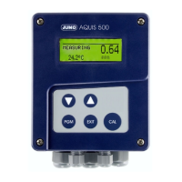
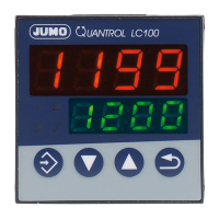
Description of device displays, LEDs, and keypad functions.
Explains parameter hierarchy and navigation between device levels.
Explanation of controller functions, including normal display and set point changes.
Parameters related to configuring the analog input, including sensor type.
Configuration of controller type, control direction, and set point limits.
Selection of the controller mode: 2-state, 3-state, modulating, or continuous.
Defines whether the controller acts directly or inversely to the process value.
Configuration of the ramp function for controlled set point changes.
Configuration of limit comparators for monitoring process values against set limits.
Configuration and operation of the timer function.
Configuration of binary and analog outputs, including switching states.
Explains functions initiated by binary signals and their switching behavior.
Configuration of displays, time-out, and restart times.
Configuration of the RS485 interface for data network integration.
Detailed technical specifications for thermocouple and RTD temperature probe inputs.
Defines output statuses during sensor faults and provides output specifications.
Lists display messages, their causes, and recommended fault remedies.
Principle and prerequisites for starting the self-optimization function.
Step-by-step guide to initiating and canceling the self-optimization process.
| Control Type | On/Off, PID |
|---|---|
| Input Channels | Up to 4 |
| Input Types | Thermocouples, RTD |
| Output Types | Relay |
| Power Supply | 24 V DC |
| Communication Interfaces | RS-485 |
| Protection Class | IP20 |
| Dimensions | 48 x 48 mm |
| Display | LCD display |