Do you have a question about the JUMO Quantrol LC200 and is the answer not in the manual?
Information on datasheets, brief instructions, and operating manuals.
Essential safety guidelines, hazards, and warning symbols used in the manual.
Details the items included in the product package.
Explains the meaning of symbols like TIP! and REFERENCE! for user guidance.
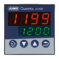
Guide to recognizing specific device models and their corresponding order codes.
Key technical specifications including case type, dimensions, and environmental limits.
Details on voltage supply, safety standards, power consumption, and connection requirements.
Step-by-step instructions for mounting the LC100, LC200, and LC300 controllers.
Important considerations for safe and proper installation and electrical isolation details.
Visual representation of terminal connections and a tip on USB interface usage.
Important warnings regarding voltage risks and the need for qualified personnel.
Table mapping various input and output types to specific terminal numbers.
General introduction to the device's operational modes and user interface.
Identification and explanation of the device's displays, LEDs, and control buttons.
Procedures for self-optimization, setpoint adjustment, and manual mode operation.
Explanation of how the ramp function and firing curve features operate.
Description of device access levels and parameters available in the operator level.
Introduction to configuration level and the options for analog signal selection.
Details on configuring various analog input types, sensors, and signal ranges.
Settings for controller type, action, output modes, and setpoint limitations.
Configuration options for ramp, firing curve, and limit value monitoring functions.
Settings for timer functions and response logic for limit value alarms.
Configuration parameters for controlling binary outputs and analog output signals.
Configuration of binary inputs for function triggering and display settings.
Settings for the RS485 interface, including baud rate and device address.
Detailed parameters for tuning the controller, such as proportional band and derivative time.
Supplementary details and tips for the installation process.
Diagrams and measurements for installing the LC100 controller.
Diagrams and measurements for installing the LC200 controller.
Diagrams and measurements for installing the LC300 controller.
Guidelines for cleaning the device's front panel safely and effectively.
Further explanations and details about the device's various functions.
In-depth information on analog input offset, filter constants, and analog output scaling.
Detailed explanation of the operational phases and logic of ramp and firing curves.
Description of timer operation for time-limited control and setpoint changeovers.
Illustrations and explanations of different limit value monitoring alarm functions.
Overview of the self-optimization process and its parameters for PID/PI controllers.
Details on self-optimization methods, required conditions, and controller setup.
Procedures for initiating, monitoring, and terminating the self-optimization process.
List of error displays, their causes, and recommended solutions for troubleshooting.
Specifications for thermocouple and RTD temperature probe inputs.
Specifications for standard signal inputs, binary inputs, outputs, and monitoring.
Data for controller structure, electrical characteristics, cable requirements, and case.
Specifications on site altitude, interface, display features, and product approvals.
| Type | Process controller |
|---|---|
| Protection Class | II |
| Outputs | 2 relay outputs |
| Communication | RS485 Modbus RTU |
| Control type | PID |
| Housing | Plastic |
| Protection type | IP20 |
| Relay Outputs | 2 relay outputs |
| Inputs | 2 universal inputs (thermocouple, RTD, voltage, current) |
| Power Supply | AC 110 to 240 V +10 % / -15 %, 48 to 63 Hz AC/DC 20 to 30 V, 48 to 63 Hz |
| Supply voltage | AC 110 to 240 V +10 % / -15 %, 48 to 63 Hz AC/DC 20 to 30 V, 48 to 63 Hz |
| Analog Inputs | 2 universal inputs (TC, RTD, 0/4-20 mA, 0-10 V) |