Do you have a question about the JUMO IMAGO F3000 and is the answer not in the manual?
Details on instructions validity, warranty, technical data, and documentation structure.
Explanation of warning signs, note signs, and text representation conventions.
Explains how to identify the instrument's specific model and configuration via its type code.
Lists package contents, optional accessories, and plug-in boards for expansion.
Provides physical dimensions and instructions for securely mounting the instrument in a panel.
Essential guidelines and safety precautions for electrical connections and wiring.
Detailed diagrams showing electrical connections for various modules and slots.
Diagram illustrating electrical isolation levels between different instrument components.
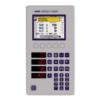
Detailed view of the IMAGO F3000 display and its interactive control elements.
A graphical overview of the instrument's operational states and transitions.
Describes the basic status screen and details on designing and entering programs.
Instructions for initiating programs, including selection, linking, and quick start options.
Covers automatic operation modes, pausing, and temporary alterations.
Manual operation, stopping programs, and understanding program end signals.
Overview of configuration levels, menu structure, and interface setup.
Editing process steps and setting temperature units for display.
Managing passwords and performing system parameterization settings.
User settings, counters, and managing access to instrument functions.
Features and applications of the P&P memory for configuration, backup, and updates.
Procedures for writing data to P&P memory and enabling automatic saving.
Instructions for enabling or disabling write protection on the P&P memory.
Steps to copy programs from one P&P memory or instrument to another.
Procedure for replacing a faulty instrument using the P&P memory.
Covers retrofitting, backups, commissioning, OEM programming, and loading protected data.
Steps to load new instrument software onto the P&P memory.
Configuration options that can only be set directly on the instrument.
Managing access levels, device lists, and hardware configuration settings.
Defining program steps, editing process sequences, and customizing screen layouts.
Configuring instrument interfaces and special settings for communication modules.
Configuring analog inputs, probe types, and controller parameters.
Methods for core temperature acquisition and setting program running parameters.
Detailed controller parameter settings and configuring limit comparators.
Parameters for configuring smoke generators and conveyor screws.
Settings for screen saver, instrument designation, language, passwords, and date/time.
Overview of settings configurable only via the setup program, including displays, keys, texts, and outputs.
Configuring 7-segment display values and assigning functions to keys.
Defining user/system texts and naming control elements for easier configuration.
Configuring analog output signals and assigning functions to relay outputs.
Defining logic signals and alarm triggers, including message types and priorities.
Setting up fan control and defining mathematical/logical formulas for calculations.
Inhibiting operating facilities and monitoring equipment operating time.
Managing production data queries and documenting setup information.
| Brand | JUMO |
|---|---|
| Model | IMAGO F3000 |
| Category | Controller |
| Language | English |