IMAGO F3000 / 10.01 17
4 Electrical Connection
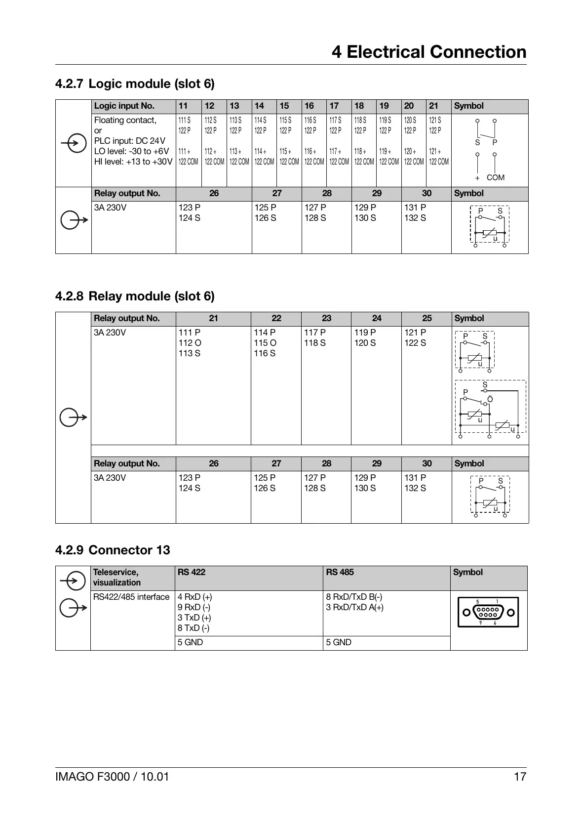
4.2.7 Logic module (slot 6)
4.2.8 Relay module (slot 6)
4.2.9 Connector 13
Logic input No. 11 12 13 14 15 16 17 18 19 20 21 Symbol
Floating contact,
or
PLC input: DC 24V
LO level: -30 to +6V
HI level: +13 to +30V
111 S
122 P
111 +
122 COM
112 S
122 P
112 +
122 COM
113 S
122 P
113 +
122 COM
114 S
122 P
114 +
122 COM
115 S
122 P
115 +
122 COM
116 S
122 P
116 +
122 COM
117 S
122 P
117 +
122 COM
118 S
122 P
118 +
122 COM
119 S
122 P
119 +
122 COM
120 S
122 P
120 +
122 COM
121 S
122 P
121 +
122 COM
Relay output No. 26 27 28 29 30 Symbol
3A 230V 123 P
124 S
125 P
126 S
127 P
128 S
129 P
130 S
131 P
132 S
Relay output No. 21 22 23 24 25 Symbol
3A 230V 111 P
112 O
113 S
114 P
115 O
116 S
117 P
118 S
119 P
120 S
121 P
122 S
Relay output No. 26 27 28 29 30 Symbol
3A 230V 123 P
124 S
125 P
126 S
127 P
128 S
129 P
130 S
131 P
132 S
Teleservice,
visualization
RS 422 RS 485 Symbol
RS422/485 interface 4 RxD (+)
9 RxD (-)
3 TxD (+)
8 TxD (-)
8 RxD/TxD B(-)
3 RxD/TxD A(+)
5 GND 5 GND
 Loading...