IMAGO F3000 / 10.01 15
4 Electrical Connection
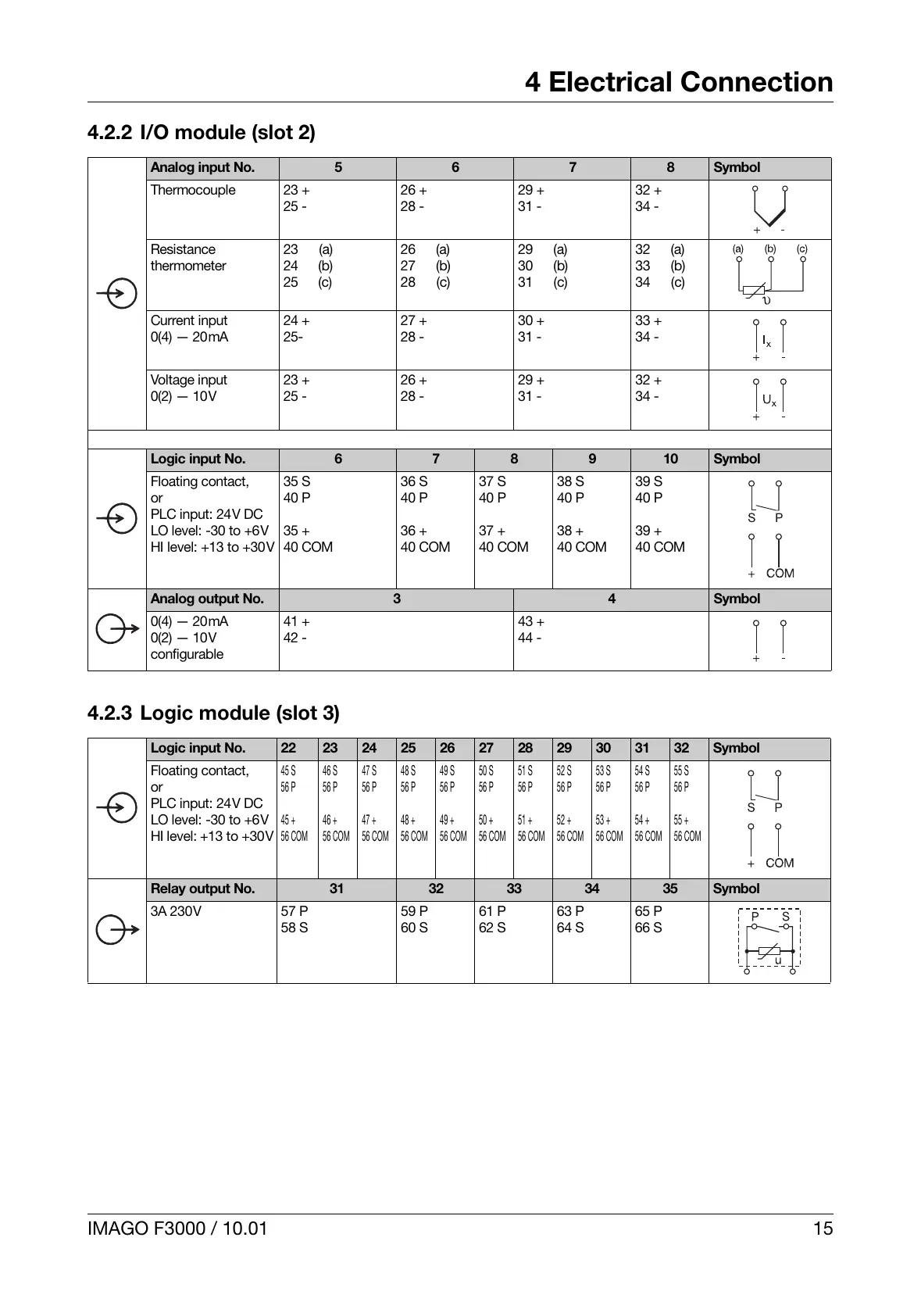
4.2.2 I/O module (slot 2)
4.2.3 Logic module (slot 3)
Analog input No. 5 6 7 8 Symbol
Thermocouple 23 +
25 -
26 +
28 -
29 +
31 -
32 +
34 -
Resistance
thermometer
23 (a)
24 (b)
25 (c)
26 (a)
27 (b)
28 (c)
29 (a)
30 (b)
31 (c)
32 (a)
33 (b)
34 (c)
Current input
0(4) — 20mA
24 +
25-
27 +
28 -
30 +
31 -
33 +
34 -
Voltage input
0(2) — 10V
23 +
25 -
26 +
28 -
29 +
31 -
32 +
34 -
Logic input No. 6 7 8 9 10 Symbol
Floating contact,
or
PLC input: 24V DC
LO level: -30 to +6V
HI level: +13 to +30V
35 S
40 P
35 +
40 COM
36 S
40 P
36 +
40 COM
37 S
40 P
37 +
40 COM
38 S
40 P
38 +
40 COM
39 S
40 P
39 +
40 COM
Analog output No. 3 4 Symbol
0(4) — 20mA
0(2) — 10V
configurable
41 +
42 -
43 +
44 -
Logic input No. 22 23 24 25 26 27 28 29 30 31 32 Symbol
Floating contact,
or
PLC input: 24V DC
LO level: -30 to +6V
HI level: +13 to +30V
45 S
56 P
45 +
56 COM
46 S
56 P
46 +
56 COM
47 S
56 P
47 +
56 COM
48 S
56 P
48 +
56 COM
49 S
56 P
49 +
56 COM
50 S
56 P
50 +
56 COM
51 S
56 P
51 +
56 COM
52 S
56 P
52 +
56 COM
53 S
56 P
53 +
56 COM
54 S
56 P
54 +
56 COM
55 S
56 P
55 +
56 COM
Relay output No. 31 32 33 34 35 Symbol
3A 230V 57 P
58 S
59 P
60 S
61 P
62 S
63 P
64 S
65 P
66 S
 Loading...