7 Setup Program
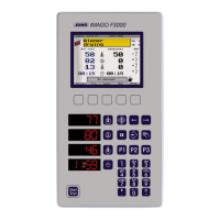
70 IMAGO F3000 / 10.01
7.5 Parameterization
7.5.1 Controller parameters
The controller parameters are used to adapt the controller to the control loop.
Controller parameter set 1 — 8
Selection/settings Description
Controller
structure
P, I, PD, PI, PID Controller structure 2 for the output of a double-
setpoint controller.
Modulating controllers can only use PI or PID.
Proportional
band
0 — 9999 Xp1, Xp2
The controller structure is ineffective if Xp1, 2 = 0 !
(thermostat function)
Xp1, 2 must be > 0 for proportional controllers.
Derivative time 0—80 — 9999 sec Tv1, Tv2
Reset time 0—350 — 9999 sec Tn1, Tn2
Switching cycle
time
0—20 — 9999 sec Cy1, Cy2
With a switching output, the switching cycle should
be chosen so that the pulsewise energy feed does
not cause impermissible fluctuations in the process
values, while at the same time not overloading the
switching devices through excessive switching.
Contact spacing 0 —9999 Xsh
Spacing between the two control contacts in
double-setpoint or modulating controllers, or pro-
portional controllers with integral actuator driver.
Switching
differential
0—1 — 9999 Xd1, Xd2
Hysteresis in switching controllers with Xp = 0
Actuator time 15 — 60 — 3000 sec TT
The time range used for the regulator valve in
double-setpoint controllers or proportional
controllers with an integrated actuator driver.
Working point -100—0—+100% Y0
Output level for P and PD controllers
(for x = w , y = Y0)
Output level max.
limit
0to100%Y1, Y2
Output level limiting restricts the controller output
signal to values between the maximum (Y
max.
) and
minimum (Y
min.
) limits.
Example: in a proportional controller
Output level min.
limit
-100 to +100%
Minimum relay
ON time
0 —60 sec TK1, TK2
Limits the frequency of output switching.
k / bold = factory setting
 Loading...