JUNCTEK
Chapter 2 Meter Introduction
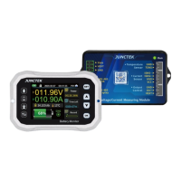
1. Introduction of display module
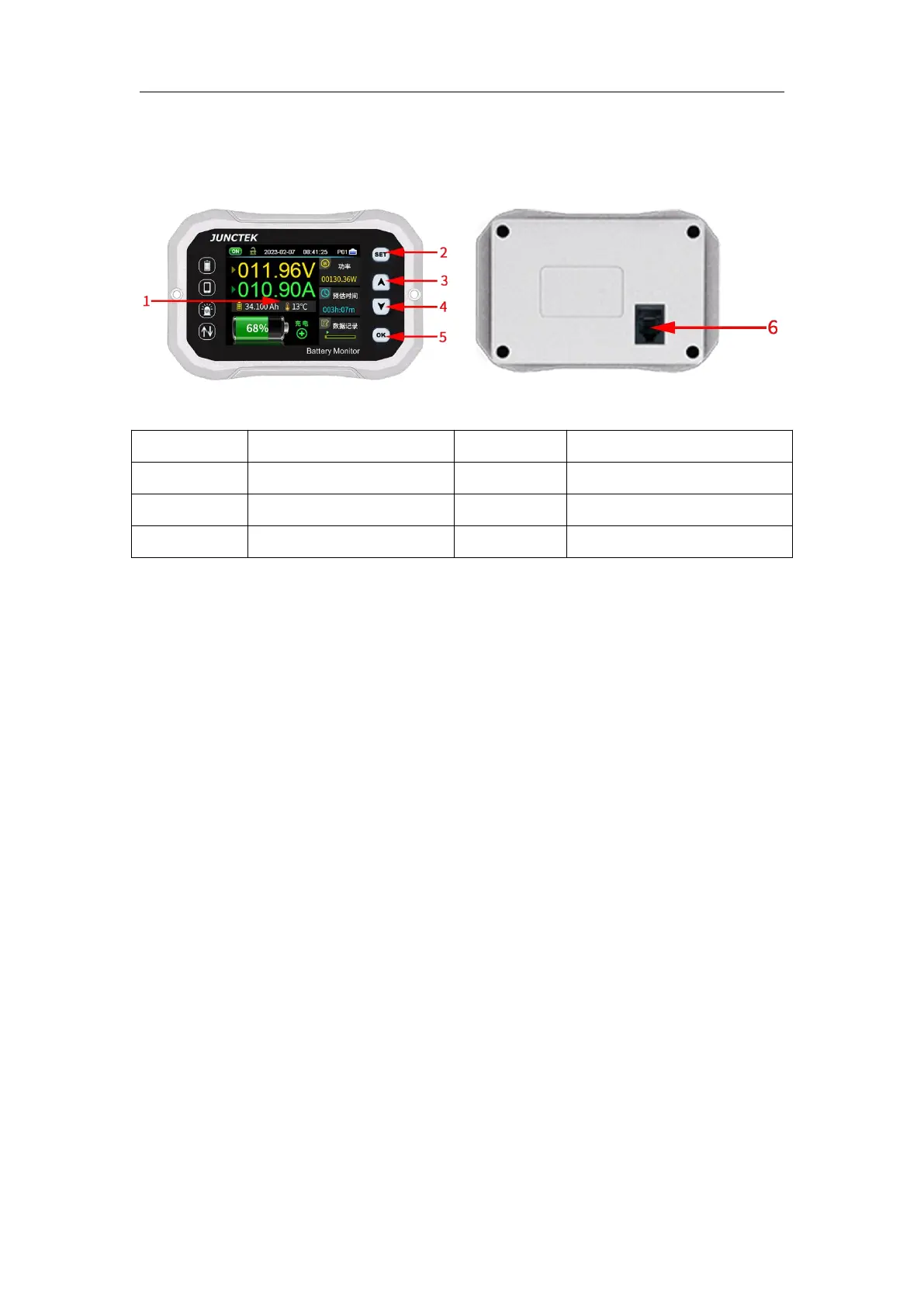
Figure 2-1-1 KH-F series display module diagram
Table 2-1-1 KH-F series display module diagram instructions
(1).LCD screen
A 2.4-inch TFT color LCD display screen shows the menu of current functions
and settings of parameters, etc.
(2).【SET】button
Pressing the【SET】button briefly can quickly switch to the settings interface;
while on the main interface, pressing and holding the【SET】button can select
the address and use the
【
▲
】【
▼
】
buttons to quickly adjust the address.
(3).【▲】button
When setting parameters, it is used to change the parameters; when in system
settings, pressing the 【 ▲ 】 button can select the corresponding system
settings; on the main interface, long-pressing the
【
▲
】
button can pop up a
current zero-point saving window to remember the zero-point current state.
Note: When the current is zero, perform the zero-point saving operation. Do
not operate when it is not zero.
(4).【▼】button
When setting parameters, it is used to change the parameters; when in system
settings, pressing the
【
▼
】
button can select the corresponding system settings;
on the main interface, long-pressing the【▼】 button can turn off the display
screen. While the screen is off, do not press other buttons. Pressing 【▼】
button again can turn the display screen back on.
(5).【OK】button
 Loading...